No that currents are normal as just the Zener diodes are a shunt PSU. Like you noticed they are not very precise in value especially when becoming hot. As said before NE5532 absolute maximum values are +/- 22V.
7815/7915 are easier, have lower part count, have better regulation and they have short circuit/thermal protection. Use TO220 heatsinks tightened (before soldering the regulators to the PCB) with M3 bolt/nut/washers and possibly isolated to avoid troubles! And they do need the output cap for sure. The input cap is debatable, depends on distance/wiring.
In difficult situations one can solder the input and output caps 100 nF directly to the ICs pins. I use 2.5 mm pitched Wima caps for that and not ceramic ones.
Last edited:

No that currents are normal as just the Zener diodes are a shunt PSU. As said before NE5532 absolute maximum values are +/- 22V.
7815/7915 are easier, have lower part count, have better regulation and they have short circuit/thermal protection. Use TO220 heatsinks tightened (before soldering the regulators to the PCB) with M3 bolt/nut/washers and possibly isolated to avoid troubles! And they do need the output cap for sure. The input cap is debatable, depends on distance/wiring.
Please bear with me, I’ve read through this thread and haven’t seen it mentioned that the +/-22v was max. Everywhere I look it says +/-15v, but I do see the datasheet does say maximum “recommended” supply, but can handle the 22v. That’s good to know. I’m going to have to look closer at this in the future, as I have omitted certain devices because of this, when they were likely could handle the voltages in the circuit.
I’m sorry, I do not understand your first sentence. What are you saying no to? Are you saying the current eye measured is normal? Are you saying no to the Zener being a 1/2w as I asked?
Dan
No the thingies called Vcc+ and Vcc- in the schematic. The amplifiers supply rails.
If you solve the issue at the root also stable +/- 15V is no issue anymore.
BTW NE5532 has a maximum voltage of +/- 22V.
It is volts in V BTW. Also not w and hZ and such non standard contraptions. V, A, W, Hz, kW, kOhm etc. Please.
The Zener diodes just with resistors are shunt supplies always consuming power. Within the set current the load takes its current. So even without any load the Zener diodes with resistors will consume power and generate heat. It is a stupid design practice. When either one of the Zener diodes says goodbye to life the opamps will suddenly have + or - 30V which they won't survive.
(30 - 15)/180 = 0,0833A. (0,083 x 0,083) x 180 =1,24W for the resistor. Times 2 as there is also the negative supply. And also for the Zener diodes themselves. Fast calculation as I am busy but that is around 5W burnt to useless heat.
Just use the 7815/7915 as it works out of the box.
NE5532 is recommended for +/- 15V use but their absolute maximum supply voltages are +/- 22V. +/- 24V will likely kill them in minutes or even seconds. They are not meant to be used for longer time on higher design voltages than +/- 15V but allow voltage peaks/deviations. If they would have been used for longer time on +/- 21V I would be suspicious. If unsure just replace as these cost nothing. Or replace them for something better and have another 20 pages on that 🙂 If they still work OK just leaving them be is an option.
Last edited:
It is volts in V BTW. Also not w and hZ and such non standard contraptions. V, A, W, Hz, kW, kOhm etc. Please.
The Zener diodes just with resistors are shunt supplies always consuming power. Within the set current the load takes its current. So even without any load the Zener diodes with resistors will consume power and generate heat. It is a stupid design practice. When either one of the Zener diodes says goodbye to life the opamps will suddenly have + or - 30V which they won't survive.
(30 - 15)/180 = 0,0833A. (0,083 x 0,083) x 180 =1,24W for the resistor. Times 2 as there is also the negative supply. And also for the Zener diodes themselves. Fast calculation as I am busy but that is around 5W burnt to useless heat.
Just use the 7815/7915 as it works out of the box.
NE5532 is recommended for +/- 15V use but their absolute maximum supply voltages are +/- 22V. +/- 24V will likely kill them in minutes or even seconds. They are not meant to be used for longer time on higher design voltages than +/- 15V but allow voltage peaks/deviations. If they would have been used for longer time on +/- 21V I would be suspicious. If unsure just replace as these cost nothing. Or replace them for something better and have another 20 pages on that 🙂 If they still work OK just leaving them be is an option.
Is this in reference to my occasionally not capitalizing abbreviations? I do under stand “V” is volts, but “v” does get the point across. I will certainly work on that. I generally do capitalize, but sometimes when I use talk to text I skip over making those corrections. I don’t believe I have ever in my life done a reverse capitalize like “hZ” in your example, that’s just dumb. But I appreciate you keeping me on my toes, I will keep it correct.
You explaining the shunt to me makes perfect sense, thank you for explaining it that way. The zener is always pulling voltage to ground, thus wasting energy. That makes sense that when it decides to go open, all the silicon will go bye-bye. If it goes short, it’ll then open up the resistor? Or catch fire?
I have some more sockets coming today and plan on placing them in where the TL072 sit. I have many TL072 and NE5532AP on hand, so I will be placing new ones in after I get the voltage settled just to see if that will relieve me of the problem of going into protect as soon as it sees a signal. After I get that settled in I very well may put better opamps in, don’t know. The thing is, I have many amplifiers that are far superior, I have at least 30 amplifiers, probably more. What makes this one special is its small form factor. The amplifier strictly be used for testing purposes, so it doesn’t need to be all that “awesome”. if I want to test out a new preamp or a pair of speakers and don’t want to haul an 80 pound amplifier up the stairs it would be nice to grab this little guy which will do the job nicely. so all I want is really for it to be reliable and putting in a better form of regulation would certainly do that.
Dan
Well, only some devices will fail at that level, there will be a lot of spread between devices, the point is keep below the abs max if you don't want device failures in the field. +/-17V or +/-18V was commonly used in mixing desks for these NE553x chips. The limiting factor turns out to be heat dissipation: +/-20V would tend to lead to premature failures in the field due to heat (mixing desks don't have cooling fans typically (should be obvious why), and an NE5532 pulls 8mA). Given these chips need about 3V headroom at each rail, +/-17V allows +/-14V signal peaks (10Vrms). +/-15V would reduce this to 8.5V rms. In EQ circuits with non-trivial Q this headroom is important. And +/-17V is friendly to TL072's (which have less current draw so don't get hot, but have a lower abs max voltage of +/-20V). Old analog mixing desks are typically full of TL072's and NE5532's+/- 24V will likely kill them in minutes or even seconds.
I had the same issue when working on car amplifier. It sounded great with speakers, but measured badly. Turned out one channel was inverted and you could not connect grounds together.So I think the amplifier is working. The reason it kept going into protection is because I believe one of the channels is wired out of phase which meant the ground probe of my scope was on the positive of the output.
I am not sure why this is, maybe because of the ability to be bridged. I disconnected my probe from one channel in order to trace a signal through the amplifier, and as I turned up the volume, I noticed I was getting a wave form on my scope from the one channel that was still hooked up.
View attachment 1383112
So I thought great I am one channel that is working. I picked up ground from the inside of the amplifier and found I had a single going into the other channel input. That’s when I noticed that the black wire that connects to the negative of the channel is actually connected to the speaker relay. if I stuck my probe onto the red positive wire, I saw nothing on the scope, but if I touch the black wire, I get a signal. It is out of phase of the other channel.
View attachment 1383113
View attachment 1383114
I looked for some photos online and saw the inside of somebody else’s amp and sure enough that that amp was wired exactly like this one with the red wire on top. It is kind of hard to see, but if you look closely, you can see the red wire is connected to the top screw terminal.
View attachment 1383115
So is this right? As I thought about it, it made sense to me, since it’s out of phase when I touched my probe to the black wire that would mean it would be in phase when hooked up to the speaker terminal.
Tomorrow morning, I’m going to hook up the dummy load and I’m going to use a scope that is battery powered, so there will not be a ground to short the output. If on the battery powered scope I see two signals that are in phase with each other then I will know the issue. The entire time was the way the amplifier is wired and my scope ground causing the issue. I will report back in the morning.
Dan
Yes, its for easy bridge mode.
Dan, TL072 is a clear downgrade. Just like using IC sockets.
First make the PSU mod and the repair (I haven’t looked at that). Then opamp fiddling.
If you want it small and for testing purposes that your other 30 amplifiers can’t do a nano amplifier by SMSL or a BRZHifi cost way less than this repair and they are way smaller too. They are very light as well and some may sound better than you’d expect. The crazy discovery that the test amplifier is better than the official one 😉 And you’ll have even more amplifiers so 31 to pick from. An uneven number so definitely a 32nd should follow.
Last edited:
That is actually what made it click in my head was from a car amplifier. I fixed and ran into that same issue.I had the same issue when working on car amplifier. It sounded great with speakers, but measured badly. Turned out one channel was inverted and you could not connect grounds together.
Yes, its for easy bridge mode.
Dan
Dan, TL072 is a clear downgrade. Just like using IC sockets.
First make the PSU mod and the repair (I haven’t looked at that). Then opamp fiddling.
If you want it small and for testing purposes that your other 30 amplifiers can’t do a nano amplifier by SMSL or a BRZHifi cost way less than this repair and they are way smaller too. They are very light as well and some may sound better than you’d expect. The crazy discovery that the test amplifier is better than the official one 😉 And you’ll have even more amplifiers so 31 to pick from. An uneven number so definitely a 32nd should follow.
What?!?! Using a socket is a downgrade? I had never heard that. I heard it was better since he didn’t expose the IC to high levels of heat. I even ordered the really nice machine, gold plated sockets. Well, once I get everything working properly, I will remove the sockets and put the chips directly into the board.
I hear where you are coming with the amplifier, I actually used to have one of the small amplifiers with outboard, computer power supplies. It was definitely decent. This is taking me more time than anything really, I’m not really having to spend any money on it other than parts. I already have in my parts bin. Plus, as I see it, it prevents a piece of electronics from being trashed. I’m sure the other amplifiers are fantastic, but I do like how this is a standard class AB using discrete devices versus an output class D chip.
Dan
You just explained in post #84 that you did not care about its sound quality so topology should be least relevant. Light and small were the relevant parameters.
So this being the current power supply, if I were to wire in the voltage regulator what would be the best way of going about it?

I would remove the two large 180 ohm resistors (R79 and R80) and place jumpers there. I would remove the two Zeners (ZD2 and ZD3). Should C27 and C28 stay where they are and the input to the 7815/7915 Connect right after those 470 µF capacitors? What a different value would be better? I guess I would have to change them anyway since they are only 16v (I put 25v, but would need to be 35v now) so I worry about them being able to physically fit. I tried 470 at 35 V and they were too tight of a fit. I could possibly get it to work though.
Anyways, after that the ground pin of the regulator would go to ground obviously, and the output would connect to where the 15 V marker and the Zener currently meet. There should be a small capacitor at the output of the regulator going to ground as well correct what would be a good value here?
Dan
From schematic so no idea of real life 3D but that is up to you.
- Remove R79, R80, C27, C28, ZD2 and ZD3.
- Replace C27 and C28 for normal electrolytic caps (not ultra low ESR) 22 ... 47 µF 50V. If Panasonic FC (= ultra low ESR) then use 10 µF 50V.
- mount screw type isolated heatsinks before any soldering to 7815/7915.
- find an adequate place where they won't heat up caps. Try to have the heatsinks mounted so that the fins are vertical.
- 7815: input at the point of the red cross. Output of the 7815 to the + of C27.
- 7915: input at the point of the red cross. Output of the 7915 to the - of C28.
- Connect GND of both 7815 and 7915 to the point where the - of C27 and the + of C28 connect.
- translate this all to shortest possible connections and practical tidiness in real life.
- beware of the fact that 7815 is I-GND-O and 7915 is GND-I-O
Last edited:
You just explained in post #84 that you did not care about its sound quality so topology should be least relevant. Light and small were the relevant parameters.
Topology as in being discrete would mean that it’s more easily repaired. I have an output transistor short or go open. I can easily make that repair by finding the faulty components and replacing them with a class D chip either have the chip or find out what else is wrong with the circuitry. I have worked on a few class D power supplies and class D amplifiers and me discrete is easier. Yeah, I’ve heard classy amplifiers the sound fantastic so I wasn’t referring to sound at all.
edit: I should explain, I have had class D amplifiers, small ones, that broke on me. at the time, I absolutely did not work on surfacemount at all and cannot fix the amplifiers. I now have many, many hours on surface mount work so it would likely be a different outcome. As long as I was able to get the proper parts, I would be able to fix it. it was just so stupid though, I had an amplifier I really liked made by one of the more prominent small amplifier companies. It died because I plugged the power supply in it while plugged into the wall. I put the barrel jack into the amplifier with the power supply plugged into the wall and it killed the amplifier. I was so pissed, that would never happen to AB.
Dan
Last edited:
7815: input at the point of the red cross. Output of the 7815 to the + of C27.
7915: input at the point of the red cross. Output of the 7915 to the - of C28.
Awesome, I guess that makes sense and would allow me not have to replace C27 and C28. Everywhere I looked online of example schematics. It showed a bigger capacitor on the input and a smaller on the output, but since you’re saying, otherwise I’m guessing it’s OK to do it this way.
Dan
C27 and 28 do not need to be that big with the regulators. It will slow down the start-up unnecessarily as the regulators go into current limit mode till the caps charge. The recommended 22 uF will ensure that you will stay out of the “keep out zone” of output capacitance. With somewhere between 100 pf and 100,000 pf, and depending on load current, the stupid 7915 will oscillate. Keep the output caps well north of 0.1 uF and it will stay stable with any load and added stray capacitance. The 22 uF aluminum electro should have enough ESR to keep the start up current spike under control. A 22 uF film cap would be a Bad Idea, as it’s ESR will be near zero and also have inductance to deal with giving potential for ringing at start up.
C27 and 28 do not need to be that big with the regulators. It will slow down the start-up unnecessarily as the regulators go into current limit mode till the caps charge. The recommended 22 uF will ensure that you will stay out of the “keep out zone” of output capacitance. With somewhere between 100 pf and 100,000 pf, and depending on load current, the stupid 7915 will oscillate. Keep the output caps well north of 0.1 uF and it will stay stable with any load and added stray capacitance. The 22 uF aluminum electro should have enough ESR to keep the start up current spike under control. A 22 uF film cap would be a Bad Idea, as it’s ESR will be near zero and also have inductance to deal with giving potential for ringing at start up.
I swapped C27 and C28 out for 22uF caps. I really didn’t know how to attach the regulators as there is no room physically on the board. I mounted them to small pieces of board and ran wire, then attached the wires to the appropriate place.
I have them currently sitting on top of the transformer, using a thick foam double sided sticky tape which is working well enough for now.
The first power up didn’t go well, heard a “ffftttzzzzz, POP!” I now have a cracked 7915
I made the stupid mistake of assuming that the 7915 had the same pinout as the 7815. I mean, why don’t they have the same pinout lol? Generally transistors and their complements have the same pinout. Oh well, lesson learned, will swap out the 7915, rewire and power up again.
Dan
You seem not to be a good reader or is English not your native language? Exactly this error was easily avoided. In some devices this would have cost a woofer.- beware of the fact that 7815 is I-GND-O and 7915 is GND-I-O
Anyway the 78xx/79xx always need decoupling caps close to their output pins and sometimes also at their input pins (certainly with extension wire practices). It is all in post #92 and their datasheets.
With a pair of new ones the lead wires probably can be bent so that the regulators do fit where the resistors were. Or way shorter solid wire could be used to make it rigid extension wires directly on the PCB.
Or an aluminium strip bent so that it goes over the main caps and serves as a bracket for 78xx/79xx with PCB. Or.....
Last edited:
Well I’m college educated and read recreationally and was born in the US to English speaking parents. So you’re incorrect on your first two assumptions. It’s more likely I just missed reading the warning you gave. I see that you edited that specific post on the 23rd after my last post on the 23rd and have not been back here since. Not sure if you added it last minute, it doesn’t matter clearly I just didn’t see it. Cost a woofer? I’d hope someone making a conversion like this would be doing testing power ups with a speaker connected to the outputs.You seem not to be a good reader or is English not your native language? Exactly this error was easily avoided. In some devices this would have cost a woofer.
Anyway the 78xx/79xx always need decoupling caps close to their output pins and sometimes also at their input pins (certainly with extension wire practices). It is all in post #92 and their datasheets.
With a pair of new ones the lead wires probably can be bent so that the regulators do fit where the resistors were....
Are you saying that I should move the 22 uF caps that I put on the board closer and mount them on the small board the regulator is mounted on?
There really is now way to mount them to the main board without some type of jumpers. Where the legs connect, the spacing is just too large. Especially on the negative rail side there isn’t much room for a heatsink mounted to the back of the regulator.
Dan
OK you are a good reader 🙂 It is important to have shortest possible connections in a mechanically sturdy way so the thinking process should focus on that.
Again I mentioned ways to do that. Indeed after changing my post as advices should work out OK IMHO. So thinking before and after action.
About connecting woofers. Everyone doing such a conversion should also know differences in 78xx and 79xx 😉
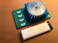
If there is space at the other side of the board maybe there is an opportunity. Just received these for a similar conversion:
Again I mentioned ways to do that. Indeed after changing my post as advices should work out OK IMHO. So thinking before and after action.
About connecting woofers. Everyone doing such a conversion should also know differences in 78xx and 79xx 😉
If there is space at the other side of the board maybe there is an opportunity. Just received these for a similar conversion:
Attachments
Last edited:
- Home
- Amplifiers
- Solid State
- I just want to confirm this behavior is normal, Zeners immediately shoot to 250 degrees F