Is your scope AC coupled?
I guess I'd install the board that passes the B signal for quick insight.
Good luck!
I believe it’s actually DC coupled at the moment. I can AC couple it if you wish.
Would it be beneficial to only wire up pin 10 and ground? Or do the whole header?
Dan
DC coupling is best here. The scope waveforms are what I'd expect at the bases of Q3 or Q5 rather than at the "A" terminal. Probably not worth a lot of attention at this point.
Thanks @mikeAtx! If I'm not lost in the maze, the A and B signals show up at an LM324, U5-D. In turn, this prompts the question what is nearby switch SW5 about? [This opamp output drives the Q8 enable.]
With this info, I think a low-risk experiment would jumper the A and B paths that flow through the PA board. Then power could be applied without installing the PA board. I still suspect a significant fault somewhere in +/- 15 powered circuits that drags down +15 rail. Please check my thinking.
Last edited:

Post #19 shows Zener outputs at +18.2 and -18.4 volts,slightly jumping the absolute max rating of the LM324 and other opamps they power(hope they have survived).This is with the standalone psu board.
Why aren't the zeners regulating to their rated +-15V?
Switch SW5 seems to be some "Auto Turn On" system based on signal presence.
It's mentioned in the op. manual here Jamo MPA101
So just pulling up point B on the psu board to the positive zener would enable the Q15 output.
Or if connecting the PA board,it's switch(SW5) could be left at the "ON" position to turn on the psu.
DC coupled it will stay. so I jumper the “B” and “C” connectors as well as plugged the input board pin header. I can’t physically see them, but all of these ICs must be on that input board.DC coupling is best here. The scope waveforms are what I'd expect at the bases of Q3 or Q5 rather than at the "A" terminal. Probably not worth a lot of attention at this point.
Thanks @mikeAtx! If I'm not lost in the maze, the A and B signals show up at an LM324, U5-D. In turn, this prompts the question what is nearby switch SW5 about? [This opamp output drives the Q8 enable.]
With this info, I think a low-risk experiment would jumper the A and B paths that flow through the PA board. Then power could be applied without installing the PA board. I still suspect a significant fault somewhere in +/- 15 powered circuits that drags down +15 rail. Please check my thinking.
Everything looks to be about the same. I still have the +12, I still have both -15, but only have one +15 V rail still missing the other 15 V. Any reason to hook up the “D” jumper?
As I wait to hear back from you folks, I think I’m going to pull the input board out. I would be inclined to agree there is a fault on the 15 V rail so I will check the ICs for any shorts or anything.
Dan
If you applied power, what voltages diid you observe at U5-pin 14 (i.e. B) and at Q8 collector? If U5-pin 14 isn't around +10V, what voltages on U5 power rails and voltages at U5-pins 12,13,14?
Post #19 shows Zener outputs at +18.2 and -18.4 volts,slightly jumping the absolute max rating of the LM324 and other opamps they power(hope they have survived).This is with the standalone psu board.
Why aren't the zeners regulating to their rated +-15V?
Switch SW5 seems to be some "Auto Turn On" system based on signal presence.
It's mentioned in the op. manual here Jamo MPA101
So just pulling up point B on the psu board to the positive zener would enable the Q15 output.
Or if connecting the PA board,it's switch(SW5) could be left at the "ON" position to turn on the psu.
I read that the auto on switch can be a source of problems and is recommended to keep it in “ON” vs auto.
I read that the auto on switch can be a source of problems and is recommended to keep it in on auto.
Yeah the voltage is a bit higher than I wish it to be. Because of this, I replaced some of the 16 V capacitors with 25 V rated. At least until I get this all sorted. I hope none of the bad either.
@Sashi makes a good observation: tacking B to +15V zener would enable Q15--- simpler than connecting the jumpers I suggested earlier.
Since I I already placed the jumpers, I’m good on that point???
I pulled the input board to check it out.
Here I am measuring the resistance from ground to +15 V rail on each of the chips.
But I am getting an odd reading on one of the chips, and maybe this is the problem? It’s an LM324N. According to the pinout the +15v is pin four. And directly across from it should be ground, pin 11.
On this IC pin four does indeed look to be directly connected to the +15v. Pin 11 has no continuity to ground at all. It’s actually pin 10, the third pin up from the bottom where I get a short to the 15 V rail and a short to ground. You can see my probe is touching the switch body and my other probe is on pin 10 of the chip. Is it possible that the chip lost ground so then one of the inputs shorted to ground? I don’t really get what’s going on here.
Oh, and I plan on replacing some of the capacitors on this board. I get his intentions, but some of these are just for smoothing and would do well with something like a Panasonic FR. These are just too big physically.
Dan
B also goes to a tiny board with a transistor, resistor and diode and creates C & F. And good catch, 324 not 339. I guess I was thinking it must be a comparator switch for the P/S. I'm kind of lost on what they are trying to do.
B also goes to a tiny board with a transistor, resistor and diode and creates C & F. And good catch, 324 not 339. I guess I was thinking it must be a comparator switch for the P/S. I'm kind of lost on what they are trying to do.
I was going to ask if they were in any way compatible, I have more 339s then I would ever need for 100 lifetimes. Not sure if I have a 324 though. I cannot find that tiny board, it must be a part of one of the bigger boards? It’s weird that they didn’t give any of those devices board position numbers.
Dan
I've not found specified where pin 11 of the LM324 is connected, but predict that it's tied to -15V Zener; that would allow pin 14 to swing to the negative rail and disable both Q7 and Q15.
LM324 and LM339 are different animals, different pinouts, and won't swap.
LM324 and LM339 are different animals, different pinouts, and won't swap.
I've not found specified where pin 11 of the LM324 is connected, but predict that it's tied to -15V Zener; that would allow pin 14 to swing to the negative rail and disable both Q7 and Q15.
LM324 and LM339 are different animals, different pinouts, and won't swap.
Yeah, I figured, I took a look at the data sheet and figured it wouldn’t work. I was rebuilding the board and found the short. It was coming from a capacitor he had placed in there, you couldn’t see it from the top side, but the legs must’ve been touching or something. as soon as I removed the capacitors, I was planning on swapping out the short went away. Before I had replace the capacitors, I removed three of the chips and found the short had not gone away. I installed sockets instead of soldering them back in.
The capacitors that I replaced were C22, C23, and C24. They were all called to be 220 µF and I installed 330 µF as these are Panasonic FM and fit better than the 220 I have. I figure the extra capacitance isn’t necessarily a bad thing.
To the chips I removed are U1 and U2. It looks like they’re the first stage of amplification for the input. They are using NE5532P. Since I have them in sockets, anyone think I should try different devices? I have a ton of NE5532AP which is supposed to be a lower noise version, I could put a couple of those in there. Or maybe a couple Burr Brown ICs? Thoughts? With the short eliminated, I’m going to try to put this back together somewhat powered up and see what voltages look like.
Dan
I have it all assembled as far as wiring, boards are still hanging out off the side. Electrically it should be good to go and time for a power up.

And we have first signs of life!!!

If it’s fully functional, I’m going to steal replace our 79 since it has physical heat stress damage. Before I put the input board back in I am going to wait to see if people think I should install better quality opamps, get thoughts on that. It’s not like this is going to be an audiophiles dream, but a good test unit would be cool.
Dan
And we have first signs of life!!!
If it’s fully functional, I’m going to steal replace our 79 since it has physical heat stress damage. Before I put the input board back in I am going to wait to see if people think I should install better quality opamps, get thoughts on that. It’s not like this is going to be an audiophiles dream, but a good test unit would be cool.
Dan
I wanted to see if it was ready to go and it definitely is not. Once you power it up, it’ll stay powered up, but you breathe on it and It goes into protection. I fed a signal into it and for a split second you get output, but then goes into protection.

The signal I am feeding is 500 mV and it’s something in the amplifier sing. So something is resonating with the signal. I will power it up in a bit and check all of those voltages again to see where they are at.
Dan
The signal I am feeding is 500 mV and it’s something in the amplifier sing. So something is resonating with the signal. I will power it up in a bit and check all of those voltages again to see where they are at.
Dan
Here are the two pin headers and the voltages on the pins. I went ahead and measured every pin. All of the rails look to be in line.

Same here, all look good with what the manual says, though pin 8, the -15 looks kind of high at -17.29.

Dan
Same here, all look good with what the manual says, though pin 8, the -15 looks kind of high at -17.29.
Dan
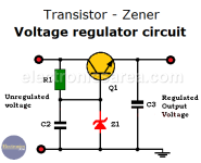
What a cheap lazy design , all they would need to do is use 2 more transistors (EF follower zener regs) to make for a real cool
aux supply. Zener can run cool with just a few mA's...
PS - and running the op-amps at 15+ V , they only need a +/- 12V supply to do what they do.
OS
aux supply. Zener can run cool with just a few mA's...
PS - and running the op-amps at 15+ V , they only need a +/- 12V supply to do what they do.
OS
Attachments
So I think the amplifier is working. The reason it kept going into protection is because I believe one of the channels is wired out of phase which meant the ground probe of my scope was on the positive of the output.
I am not sure why this is, maybe because of the ability to be bridged. I disconnected my probe from one channel in order to trace a signal through the amplifier, and as I turned up the volume, I noticed I was getting a wave form on my scope from the one channel that was still hooked up.

So I thought great I am one channel that is working. I picked up ground from the inside of the amplifier and found I had a single going into the other channel input. That’s when I noticed that the black wire that connects to the negative of the channel is actually connected to the speaker relay. if I stuck my probe onto the red positive wire, I saw nothing on the scope, but if I touch the black wire, I get a signal. It is out of phase of the other channel.


I looked for some photos online and saw the inside of somebody else’s amp and sure enough that that amp was wired exactly like this one with the red wire on top. It is kind of hard to see, but if you look closely, you can see the red wire is connected to the top screw terminal.

So is this right? As I thought about it, it made sense to me, since it’s out of phase when I touched my probe to the black wire that would mean it would be in phase when hooked up to the speaker terminal.
Tomorrow morning, I’m going to hook up the dummy load and I’m going to use a scope that is battery powered, so there will not be a ground to short the output. If on the battery powered scope I see two signals that are in phase with each other then I will know the issue. The entire time was the way the amplifier is wired and my scope ground causing the issue. I will report back in the morning.
Dan
I am not sure why this is, maybe because of the ability to be bridged. I disconnected my probe from one channel in order to trace a signal through the amplifier, and as I turned up the volume, I noticed I was getting a wave form on my scope from the one channel that was still hooked up.
So I thought great I am one channel that is working. I picked up ground from the inside of the amplifier and found I had a single going into the other channel input. That’s when I noticed that the black wire that connects to the negative of the channel is actually connected to the speaker relay. if I stuck my probe onto the red positive wire, I saw nothing on the scope, but if I touch the black wire, I get a signal. It is out of phase of the other channel.
I looked for some photos online and saw the inside of somebody else’s amp and sure enough that that amp was wired exactly like this one with the red wire on top. It is kind of hard to see, but if you look closely, you can see the red wire is connected to the top screw terminal.
So is this right? As I thought about it, it made sense to me, since it’s out of phase when I touched my probe to the black wire that would mean it would be in phase when hooked up to the speaker terminal.
Tomorrow morning, I’m going to hook up the dummy load and I’m going to use a scope that is battery powered, so there will not be a ground to short the output. If on the battery powered scope I see two signals that are in phase with each other then I will know the issue. The entire time was the way the amplifier is wired and my scope ground causing the issue. I will report back in the morning.
Dan
Just 2 extra 15V windings on the existing toroid or an extra micro/mini toroid 2 x 15V would have been the right design decision to keep stuff cool & reliable. Dropping high DC voltages to opamp voltages is a system choice based on low cost.
Since I saw/see this voltage dropping for no good reason practice so much I made mini PCBs with a molded mini toroid, rectifier bridge and series regulators. R79 and R80 and the Zener diodes then can go. All will stay relatively cool. The power to heat up resistors and Zener diodes is not needed when having normal input voltages to the regulators so the device will be less hot and consume less power.
Actual power draw of the circuit is good to know. Often is it quite low as the only reason of the heat is dropping for instance (example!) 50V to 15V at a tiny 0.05A. Yes that is 1.75W per leg of heat. That x 2 so 3.5W of heat and dying parts plus solder joints for no reason.
Last edited:
Yes, indeed it definitely looks like there is some cost-cutting in this. I know this exact same model was put out in Dayton’s name. This was definitely built to a price point and exactly as you say it seems like most faults come from heat in this thing. There’s definitely room for another small transformer, but of course, that costs more than a couple of resistors in a couple of Zeners.
I went to test it this morning and I am still having an issue, I am very certain it’s the input board. It wouldn’t surprise me if some of the chips are damaged. I have been able to get consistent results and the issue that is coming up is the signal. I was able to feed last night, but as soon as I went to feed signal, I heard some little noises coming from the input board. so the amplifier will sit there powered up just fine, but as soon as I feed Signal, I tried my Signal generator and then I tried and iPad going through headphone jack and as soon as music starts playing immediately kicks into protection. Now I am just taking a guess at it being the input board, but on that as soon as it starts, seeing a signal no matter how low that signal is it kicks into protection.
The voltage is still seem kind of high. I just checked all of the chips and they are seen +16.6v and -17.2v. The NE5532 show a max of +/- 15v. Are these voltages high enough to damage them? I was thinking of putting new chips in, but if the voltages are this high, I don’t want to damage anything new. If I went with something like the OPA2134 it would be able to handle these higher voltages. The TL072 look like they can handle handle the voltages.
Before I move onto that route, does anyone think this could potentially be an issue? I have also found that if the amplifier is sitting there powered up just fine and I brush my fingers along the backside of the board essentially making contact between the pins with my fingers resistance it too kicks into protection.
Dan
- Home
- Amplifiers
- Solid State
- I just want to confirm this behavior is normal, Zeners immediately shoot to 250 degrees F