The circuit seems not complete for a while
I have not understood how it works, because of that i could not make the needed adjustments on it.
I had, almost this same schematic, in my hands years ago... was an idea from Bridges, Anatech our moderator... and i could not fix off set and bias, reason why i have not tested his circuit.
As Dunlap said, the schematic is not new.... it appeared first time almost 30 years ago.... so, others have made, have created same time, have developed and have used too.
Wrong resistance (bias) into my schematic is because i was trying to adjust bias... i could not..... my circuit seems wrong... no feedback?
I will be following the thread with attention, and will read Dunlap text once again to find clues, tracks to deduce my doubts.
Carlos
Attachments
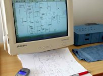
Be sure.... after 10 minutes Dunlap published
.... the entire final schematic....the amplifier will be playing here.
Life is short... i do not waste my time...i am already old.
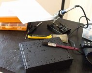
This wrong, and basic frame of the schematic will be assembled
NOW!
regards,
Carlos
.....................................................................................................
Music playing here is:
"On the road again".... country music.
The pleasure is to drive a Thunderbird, a green one...roof made using white vynil.... one of the prefered car for black folks, into the US during the seventies, the ones are clean and shinny..white folks cars are usually very dirty..... a shinny one!...leather seats...of course white seats...music loud, glasses open... a nice smile...and 100 Mph into the roads again... from Los Angeles to deep happyness... a visit to Hollywood is fine!
I just cannot forget the engine music....that's HAPPYNESS!
I have made that and i miss that very much.
heheheh.
.... the entire final schematic....the amplifier will be playing here.
Life is short... i do not waste my time...i am already old.
This wrong, and basic frame of the schematic will be assembled
NOW!
regards,
Carlos
.....................................................................................................
Music playing here is:
"On the road again".... country music.
The pleasure is to drive a Thunderbird, a green one...roof made using white vynil.... one of the prefered car for black folks, into the US during the seventies, the ones are clean and shinny..white folks cars are usually very dirty..... a shinny one!...leather seats...of course white seats...music loud, glasses open... a nice smile...and 100 Mph into the roads again... from Los Angeles to deep happyness... a visit to Hollywood is fine!
I just cannot forget the engine music....that's HAPPYNESS!
I have made that and i miss that very much.
heheheh.
Attachments

Carlos,
Is that what you were looking for? Is the music as you remembered it?
It is mind numbing to think you started this whole thing with a request originating in Brazil and through the help of a few good folks was able to find Steve and this circuit. The wonders of the internet and friends. These things never cease to amaze. And in only a few DAYS!!!
Thanks for the time and effort Steve. Will be waiting on the frontend circuit if you so choose.
Tad
Yep Tryon... i use to move.... my life into labour needed to be fast
I was the switcher, the TV Director, the Master controller from the main National Television...or you think in miliseconds and react less than a second or the station will go out from the air.
those early days you had to control all equipments, cameras and Video tapes, they have prepared and them send to you to operate into the remote control...so...or you are fast or dead!
"Move" is my way to be...nothing is good enougth if you cannot make it half the time needed..never to spend time..time is gold...if can do one amplifier a day..then try to produce two.
Daugther is coming...i have to stop before start..sorry for that...i am sorry by myself too..... she wants me to help her with Universal History...ancient Greek and Sakis (ahahahahah!) also Mathematics and English.
Will teach her fast.
When people ask you:
How do you do?
You say dear...... ME GOOD!
regards,
Carlos
Attachments
Top secret...having friends, your long arm range is unlimited
Just ask them to move.... if friends, they will do gladly.
The ones say...well..had not time.... i am busy.... well, i cannot because this, that and those.... fake friends.
Send them to hell..one way ticket...not a friend.
There are guys that do not even answer your mails... i use to give them three changes only.
regards,
Carlos
Well...daugther is already here and ex wife is asking me to
Go to Ford, Fiat, Volkswagen and Chevrolet to select a new car with her... she wants to change her car.
Well... will be very busy today...but if i have 20 minutes free i will assemble this pre- schematic...will be easier to change it latter to the real values...also add subcircuits.
I am sorry guys...but i will be back!
regards,
Carlos
.................................................................................................
The car we have is Volkswagen Gol, 1 litter, 70 horsepower, 16 valves, complete, 4 doors and air conditioned and all features.... year is 2000.... value today is 7000 USD.... we will have to give this one and to pay more 12.000 USD to have the new one.
Automobiles here have enormous taxation...more than 70 percent of its price are taxes.
regards,
Carlos
Well first I have to say OOPS. The 1uF cap Is in the wrong position. It should connect between the bases of the Darlington output pair. R4 should be a 10K variable resistor. Start with it set to lowest value and increase to set bias.
Carlos:
Of course it needs gain. I said it was the output only. Offset is mostly controlled by transistor matching. There is an easier way and I will get into that as the circuit progresses.
Ask by Lumanauw:
1. Anode of D1 (//withR4) and cathode of D2, are they only going to bases of transistors, and not going anywhere else? This mean the current passing thru D1 and D2 only come from leaking current from transistor bases?
That is correct. With the transistors I am using this is about 80uA.
2. The emitor of first darlington, they connect just to base of second darlington. There is no resistor to the output node.
Is this on purpose to prevent turn-off (no discharge path for base charge of final transistor due to no resistor from base of final darlington to output node) or is this because the above drawing is only a basic schematic?
Yes this is on purpose. This may be a basic schematic but it will work.
Ask by AKSA:
As I see it, the two current sources do around 12mA each, but as one output side turns on hard, increasing Vbe, the bias voltage between the two Darlington bases remains essentially constant, and so the inactive side turns off, the more so since the current through the bias diodes actually decrease owing to the drive current into the active darlington base (usually not more than 2mA max).
I don't how you get 12mA. With the values shown the current (real world) is 10.4mA. Yes the current through the bias diodes varies with output drive.
This means that the crossover disjunction is slightly better than most Class AB amps, but the switch off of the inactive side is still an issue, surely? Or am I missing something?
You're missing something.
I'm presuming that V1 is the AC input source, not a DC source?
I don't listen to a lot of DC.
Thank you for taking the trouble to post this circuit. It's worth discussing in some detail,
Cheers,
Hugh
How about posting yours and we can discuss it also.
Posted by destroyer x:
As Dunlap said, the schematic is not new.... it appeared first time almost 30 years ago.... so, others have made, have created same time, have developed and have used too.
The circuit being called Diamond Buffer has been around over 30 years. I added the Darlington output and the bias circuit over 20 years ago. It has been refined very much since then.
Steve
Is this the final schematic Steve?
It needs gain, are there more parts to attach or i have to produce a voltage gain stage?
Is this one the final one?
regards,
Carlos
It needs gain, are there more parts to attach or i have to produce a voltage gain stage?
Is this one the final one?
regards,
Carlos
This was the starting point, not the final. Yes it needs a gain stage. I explained why I didn't post mine. Use one you are familiar with so you are evaluating the output stage only.
I would be more happy having a complete power amplifier
say.... the unit that receives 750 milivolts as standard sensitivity...or from 400 to 2 volts adjustable, RMS into the input, sinusoidal input 1 Kilohertz...... input impedance from 22 to 100K ... able to drive the amplifier to transfer the maximum unclipped power into the nominal speaker impedance..with off set control and bias control... and having the option to NFB.
Maybe i am asking too much.... but this seems to me to be a power amplifier.
Are there parts missed for a while?
I have not connected the power, but seems to me the gain is one with the circuit the way shown into the schematic provided...have i missed something?
regards,
Carlos
Oh... i see it is to us to provide the entire circuit... you are offering the output
only.... hummmm, this reduces my interest.... because i do not feel myself able to produce the great job you have done what your already have done to your designed amplifiers... so.... not having a good chance to match the great sonics you have achieved.... i will think twice to continue.
Will be watching more clever, more skilled, more experienced, more prepared folks to develop something.
But thank you very much anyway.
regards,
Carlos
There are many gain stages on this site. I thought you would have built one you could use with this output stage.
Give me a day or so to draw and post the one I use.
Give me a day or so to draw and post the one I use.
I will have to wait till December when op amps will arrive my home.
Some Op amps will arrive, some high speed modern ones, including some Burr and Brown or the same top quality units.
They were gifts made by Sean, the Anonimous into this forum, he sent to my friend Duda that has a company (acoustics enginneering project) in Washington DC..... Duda will travel to Brazil to visit family during Christmas...then he will mail them using internal Brazilian mail system (no customs problems, very fast, competent and reliable...excelent internal mail system!) and they may arrive first days of 2009.
In 24 hours we can have any package sent by internal Brazilian mail... from extreme north to extreme south.. watch the map and you see it is a very big distance...maybe the same as the distance you have from East to West in USA...or East to West in Australia.
When folks wants to send me a transistor, or a board, or something small...then Dudainc enters the thread and offer his help to bring them to my hands.
Till next year i cannot try your schematic because this op amp there.
I have some 4558 or something that has numbers alike this one (maybe a little different)... those ones i have are very old, performance may not be interesting.... even possible to use them but i will never trust that i would be achieving the same performance you have achieved into your amplifiers... the modern Op amps are said to be much better than those old folks.... as i am not skilled about them i have to belief those things people say... even knowing 99 percent are Myths created by our "exotic and fashion" community.
Unfortunattely parts are problem here.... IBGTs, Lateral Fets, complementary Fets, Mosfets, Op amps, some power audio Integrated Circuits...all that stuff is complicated to find here.... because of that i concentrate my search using BGTs only.... I have some Fets.... all them P type i think.
I love your sound...i have to say that...but i use to talk true things too.... i do not like this schematic... a hell confused... i see this as " the price we have to pay to listen a special sound"
Thank you by the schematic... kind from you to share your precious things with us... but not feeling myself confortable about this schematic.
I have failed trying to produce and adjust another Diamond Buffer schematic provided me by Anatech some years ago.... i have faced problems i could not find solution... anatech provided me part of the schematic... i was not able to acomplish the task to put it to work in a stable way, had off set problems, had gain problems, had biasing problems...well... i had almost all world problems that made me give up.
Was just an idea from Anatech...something not tested, not entirelly made...he gave me to try, as an exercise..was kind from him...i was not good enougth.
I felt ashamed, and said him would try once more... i had never the courage to face the frustration once again.... the second try never happened.
regards,
Carlos
new design
Hi mr DX ! I've seen some of your creations on youtube-very good. I have built an effecient class a push-pull amp with incredible frequency reponse,clarity etc. You may know of it. It first appeared in hifi news&rcd review 1967! by a mr Read. needs 3 pwr supplys!
Hi mr DX ! I've seen some of your creations on youtube-very good. I have built an effecient class a push-pull amp with incredible frequency reponse,clarity etc. You may know of it. It first appeared in hifi news&rcd review 1967! by a mr Read. needs 3 pwr supplys!
- Status
- Not open for further replies.
- Home
- Amplifiers
- Solid State
- I have found a special amplifier, am trying to contact the designer