This refers to the above questions on volume control and impedance matching:
The UcD180 has a 100K input impedance, check if this is correct for the HcD400 as well.
If you use a 100K volume pot connected to a low impedance source, the impedance seen by the UcD opamp input as you rotate the pot wanders between 0 and about 20K. With a 200pF capacitance, you would get a -3 dB corner frequency of 40 KHz. Not so bad. Just keep the shielded connection between the pot wiper and the UcD input as short as possible. Note that the assumed 200 pF is the total from your wiring plus the HcD input capacitance. Maybe even 100 pF is achievable, which would extend your worst case corner frequency to 80 KHz. This worst case occurs when your pot is 6dB down from its maximum.
If you want to block potential DC with an input cap, you can either place it at the input of the pot or between the wiper and the UcD-input. The latter is preferable, since you get less corner frequency variation when you rotate the pot. With a 1 uF cap, you get a -3 dB frequency of 1.4 Hz.
So, a 100K pot is actually fine and should not degrade the sound, although I would personally go for 50K.
By the way, a buffer after the pot is pretty useless since the input opamp of the UcD provides essentially the same function.
Good info there. I agree, if the input impedance is 100K then a 100K pot should work just fine.
In answer to a previous post about impedance matching - you don't want to "match" the impedances. The ideal is for the load to have a much higher input impedance than the source output impedance that feeds it. If the source impedance is too high or the load's input impedance is too low you'll get attenuation of the signal, and it won't be uniform across all frequencies (the highs will get rolled off per the explanation above due to the capacitance of the interconnects and the input capacitance of the load).
In this case a 100K pot in the center position (center of resistance not rotation) would be equivalent to two 50K in parallel which is 25K. That's the worst case. A 50k pot would be better but the remote only comes with a 100k pot (6 ganged 100k pots that is).
The signal will need to be unbalanced to work with the pot however. That's the biggest drawback for me - my source is balanced.
Last edited:
ESP
.
Elliott Sound Products - The Audio Pages (Main Index)
.
Rod Elliot has written some good articles on audio basics.Can anyone tell me where I can get some good reading on input impedance matching, as a beginner I really don't have a handle on that subject. I'd just go out and buy a 100k pot & have no idea why it wasn't working properly.😕
.
Elliott Sound Products - The Audio Pages (Main Index)
.
Last edited:
cleaned the flux.
What did you use to clean the flux off?
Thank you all for the info always appreciated.
David
Last edited:
I use a 100k pot for the UCD and removed the 100K resistor, and for safety placed a 10M over the input of the op-amp to prevent a open input when the pot makes bad contactThis refers to the above questions on volume control and impedance matching:
The UcD180 has a 100K input impedance, check if this is correct for the HcD400 as well.
If you use a 100K volume pot connected to a low impedance source, the impedance seen by the UcD opamp input as you rotate the pot wanders between 0 and about 20K. With a 200pF capacitance, you would get a -3 dB corner frequency of 40 KHz. Not so bad. Just keep the shielded connection between the pot wiper and the UcD input as short as possible. Note that the assumed 200 pF is the total from your wiring plus the HcD input capacitance. Maybe even 100 pF is achievable, which would extend your worst case corner frequency to 80 KHz. This worst case occurs when your pot is 6dB down from its maximum.
If you want to block potential DC with an input cap, you can either place it at the input of the pot or between the wiper and the UcD-input. The latter is preferable, since you get less corner frequency variation when you rotate the pot. With a 1 uF cap, you get a -3 dB frequency of 1.4 Hz.
So, a 100K pot is actually fine and should not degrade the sound, although I would personally go for 50K.
By the way, a buffer after the pot is pretty useless since the input opamp of the UcD provides essentially the same function.
I use a 100k pot for the UCD and removed the 100K resistor, and for safety placed a 10M over the input of the op-amp to prevent a open input when the pot makes bad contact
Removed the 100k resisitor? I assume this is a SMD resistor on the bottom of the board.
Where in the signal path is the resistor (in series with the input or shunting the input to ground) and why did you remove it?
I want this to work as well as possible and am interested in any mods that will help. Please be as technical as possible. I'm an EE and I understand tech speak. I assume the 10M "over the input" is connected from the pot wiper to ground? I usually put a 1M from pot wipers to ground on any pot on the input to an amp for the exact reason you describe. When using a pot as the FB resistor in an op-amp circuit I ALWAYS connect the wiper to one side of the pot to limit the gain in case of bad contact.
Last edited:
Input circuit UCD180.Removed the 100k resisitor? I assume this is a SMD resistor on the bottom of the board.
Where in the signal path is the resistor (in series with the input or shunting the input to ground) and why did you remove it?
I want this to work as well as possible and am interested in any mods that will help. Please be as technical as possible. I'm an EE and I understand tech speak. I assume the 10M "over the input" is connected from the pot wiper to ground? I usually put a 1M from pot wipers to ground on any pot on the input to an amp for the exact reason you describe. When using a pot as the FB resistor in an op-amp circuit I ALWAYS connect the wiper to one side of the pot to limit the gain in case of bad contact.
Attachments
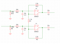
Input circuit UCD180.[/QUOTE
Removing the 100k resistor provides no real advantage. There is a small deviation from the pots unloaded rotation vs attenuation curve. Not really a problem, but rather a small improvement to the pseudo-log character. However, if the opamp has bipolar inputs, a 10M resistor will not help against temporary contact loss of the wiper. As far as I know, the FET-version is not available anymore, so you do have bipolars.
Is there a decimal point in front of the cap value? Seems to me it should be 100 pF.
The datasheet for the NE5532 indicates an input impedance of 30K - 300K. That's quite a range!
Assuming the input impedance of the op-amp inputs is 30K, the actual input impedance would be (30K+10K)ll100K= 29K
Assuming it's 300K it would be (300K+10K)ll100K= 76K
So depending on the op-amp that you happen to get the input impedance will range between 29K and 76K, not 100K
With the 100K resistor removed the numbers become 30K+10K=40K and 300K+10K=310K
It appears to me that removing the 100K resistor can help if the op-amp has a high input impedance. If you get "stuck" with a low impedance op-amp the input impedance becomes 40K without the 100K shunt, but if you get a "good" op-amp it's 310K without the 100K shunt.
To summarize that's 76K with the resistor vs. 310K without assuming a 300K input op-amp. It's 29K vs. 40K assuming a 30K input impedance on the op-amp.
Any dissention? I did this rather quickly - might have made mistakes.
Last edited:
The impedance of the opamp is in M-Ohms when connected this way. So You can assume the pot isn"t influenced by the load of the non-inverting input.The datasheet for the NE5532 indicates an input impedance of 30K - 300K. That's quite a range!
Assuming the input impedance of the op-amp inputs is 30K, the actual input impedance would be (30K+10K)ll100K= 29K
Assuming it's 300K it would be (300K+10K)ll100K= 76K
So depending on the op-amp that you happen to get the input impedance will range between 29K and 76K, not 100K
With the 100K resistor removed the numbers become 30K+10K=40K and 300K+10K=310K
It appears to me that removing the 100K resistor can help if the op-amp has a high input impedance. If you get "stuck" with a low impedance op-amp the input impedance becomes 40K without the 100K shunt, but if you get a "good" op-amp it's 310K without the 100K shunt.
To summarize that's 76K with the resistor vs. 310K without assuming a 300K input op-amp. It's 29K vs. 40K assuming a 30K input impedance on the op-amp.
Any dissention? I did this rather quickly - might have made mistakes.
But I use a 10M load to prevent a open input at bad contact. Parallel to pot-meter wiper or how do you call it.
And R1 is 330 Ohm to increase amplification about 14X same as 23dB.
thus R19 is now 10M. R5 is a jumper so we have a asymmetric input.
The ne5532 is now LME49720 in my amp.http://www.national.com/ds/LM/LME49720.pdf
Last edited:
Input circuit UCD180.[/QUOTE
Removing the 100k resistor provides no real advantage. There is a small deviation from the pots unloaded rotation vs attenuation curve. Not really a problem, but rather a small improvement to the pseudo-log character. However, if the opamp has bipolar inputs, a 10M resistor will not help against temporary contact loss of the wiper. As far as I know, the FET-version is not available anymore, so you do have bipolars.
Is there a decimal point in front of the cap value? Seems to me it should be 100 pF.
In case of non contact to pot-meter and only 10M on input then the bais current typical 10nA through 10M will cause a voltage of 0,1V.
0.1V X 14=1,4VDC a ofset of 1,4Vdc in my case.
With the amplification of the original version 6X it is a ofset of 0,6Vdc with the LME49720.
With the bias current of the NE5532 this will fail to work because it is 200nA typical.

The value 10nF is wrong it was probably the value my schematic program automatically gives the cap. It will be around 100pf like javin posted so the HF-surpression on the input has a cutoff at 150kHz.
Last edited:
Out of curiousity, how much difference do you measure between the two parts? Data I've seen suggests there's not much for well behaved loads such as the UcD180 input.The NE5532 is now LME49720 in my amp.
The impedance of the opamp is in M-Ohms when connected this way.
Not if the op-amp has bipolar inputs and not FET inputs (in general).
Check the specs. The input current shoud be in picoamps, not nanoamps. The input impedance and input current are listed in the specifications for all op-amps. The difference in the input impedance and the bias currents are several orders of magnitude apart between bipolar and FET input op-amps (again in general).
I build a lot of non-inverting preamps using FET input op-amps and when you're directly connected to the positive input the input impedance is on the order of tens of megohms. With bipolar input op-amps like this one it's more like 30K-300K per the specifications.
I didn't measure the difference I trust the spec and for the few euro the opamp cost I like to have the best.Out of curiousity, how much difference do you measure between the two parts? Data I've seen suggests there's not much for well behaved loads such as the UcD180 input.
I have a 24bit PCM1793 dac installed dc connected to the UCD I swapped op-amp there.
OP2604 LME49860 and a vintage TL072. At that time I had a film capacitor in series not DC coupled.
The OP2604 sounded the most smooth only in the middle of the soundstage it sounded a bit softer and that made the soundstage appear wider.
The LME49860 was very straight and tight sounding and the middle of the soundstage was also very clear audible.
And the TL072 was a bit less controlled what concerns the low end for high I do not remember any strange things.
Over all there was very little difference I was amazed the TL072 performed almost the same.
It makes me think does the PWM circuit of the UCD not show the differences
or is it what I do aspect is a important point, the output impedance of the op-amp in combination with the load that causes the differences I hear. Because I did the test also with a preamp and a zhalu DAC. I hear differences but what is best.
Last edited:
I didn't measure the difference I trust the spec and for the few euro the opamp cost I like to have the best.
I have a 24bit PCM1793 dac installed dc connected to the UCD I swapped op-amp there.
OP2604 LME49860 and a vintage TL072. At that time I had a film capacitor in series not DC coupled.
The OP2604 sounded the most smooth only in the middle of the soundstage it sounded a bit softer and that made the soundstage appear wider.
The LME49860 was very straight and tight sounding and the middle of the soundstage was also very clear audible.
And the TL072 was a bit less controlled what concerns the low end for high I do not remember any strange things.
Over all there was very little difference I was amazed the TL072 performed almost the same.
It makes me think does the PWM circuit of the UCD not show the differences
or is it what I do aspect is a important point, the output impedance of the op-amp in combination with the load that causes the differences I hear. Because I did the test also with a preamp and a zhalu DAC. I hear differences but what is best.
That's surprising. The TL07X series I quit using 10 years ago. The specs on the other two blow it out of the water and I can hear the difference between the TL072 and an OPA2604. The OPA2604 is a great op-amp IMHO and it does have an input impedance on the order of 8*10^12 or 8000000000000 ohms!!! The input current is in picoamps, about 1000 times less than the other op-amp.
After reading your experience I think I'll change out the op-amp on one of my modules with an OPA2604 and do some blind A/B comparisons with an unmodified unit.
The only thing I notice with my UcD180ST is some hiss, but it's only audible with your ear less than 1 foot from the tweeter. The mid and woofer drivers are silent. There is ZERO hum or buzz. I have never had an amp that didn't hum or buzz to some degree when putting your ear right on the speaker drivers. I assume it's the SMPS and the excellent PSRR of the modules. It would be interesting to disconnect the output of the op-amp and ground the trace it connects to to see how much of the hiss is coming from the op-amp or whether it's all in the output stage.
It appears the stock op-amp isn't a bad op-amp (IMHO based on my listening comparisons of the UcD180ST with other amps), it's just that the input impedance is too low for high impedance sources like 100K pots and the product has a HUGE tolerance on the input impedance. I have to believe that when using a 100K pot on the input that swapping the stock amp for an OPA2604 would make an improvement in the performance.
Then again, my beliefs often change when I actually use my ears. If I put a TL072 in the circuit and it sounded as good as the OPA2604 or even the stock op-amp I would be shocked and a little bummed out. I'd hate to think the UcD output stage masks the differences.
Last edited:
opamps
I built a preamp with opamps at unity in sockets buffering a stepped attenuator to do listening tests. The differences are quite noticeable. I was surprised how bad the TLO71 sounded. 604 and 134 are ok. not great. 627 is nice but too expensive. The best kept secret is the LT1360/61. Great sound. A little cool but very transparent. I never tried any of the newer LM opamps as I gave up on this years ago when I found out that a passive volume control with no cable following it at the amp sounded better than the best opamp. And also that my AK4395 dacs sounded best running direct out with no buffer or filter. I don't have any opamps in my signal path so have lost interest. Not that I hate them. I just don't need them. I would recommend the LM based on many posts comparing them to AD, 627 and others. Should be a step up from the 2604.
I built a preamp with opamps at unity in sockets buffering a stepped attenuator to do listening tests. The differences are quite noticeable. I was surprised how bad the TLO71 sounded. 604 and 134 are ok. not great. 627 is nice but too expensive. The best kept secret is the LT1360/61. Great sound. A little cool but very transparent. I never tried any of the newer LM opamps as I gave up on this years ago when I found out that a passive volume control with no cable following it at the amp sounded better than the best opamp. And also that my AK4395 dacs sounded best running direct out with no buffer or filter. I don't have any opamps in my signal path so have lost interest. Not that I hate them. I just don't need them. I would recommend the LM based on many posts comparing them to AD, 627 and others. Should be a step up from the 2604.
Then again, my beliefs often change when I actually use my ears.

sound hardly goes with mere specs IMO - too many things to factor in - PSU "answer", load-kick-back, source cabling...
Sometimes you can "pamper" a good unit towards extraordinary performance *if* you find out how to seriously lower the stress its specifically prone to
Michael
Last edited:
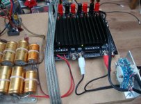
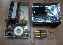
Tripad TC2000 and TK2050
I hope StigEric it doesn't bother I am writing about the tripad amp in this topic.
After some improvements concerning cooling on the Sure design because the original way of mounting is very sensitive to failure. All chips have to be mounted flat at the same hight and the heatsink has to be placed flat to ensure cooling.
It is a faulty construction. I use Bergquist Sil-Pad Products ~ Thermal Materials, Thermal Solutions ~ The Bergquist CompanySilpad to transfer heat to the heatsink. It is soft and 1mm thick to fill any uneven surface.

Donor for the project is my first build end stage from the mid 80's. It survived many crashes and experiments. Man was I nerves when buying that toroidal transformer I had to save long to get to money together and was afraid I maybe choose the wrong type back then .

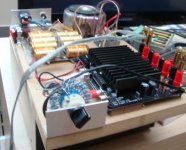
Test board 24step volume control 10Klog. 30000uF capasitors and Sure wiring and amp.


About the sound there is a difference between the UCD180 and the TK2050 the TK2050 sounds a bit more open then the UCD. And the TK2050 seems to accentuate the high detail.
I had read andrea's artikel2008 - Class D Amplifier comparasion test about class-d amp and the TK2050 sounded a bit metal like and I can't help also to describe it that way guitar strings get a bit metal string sound voices are bright. I personally like bright sound. So there for I prever the sure sound both amps perform very well but do have a differend sound what HF-range concerns.
When we look at the price four ucd modules cost 300euro and the Sure amp witch I for now prefer sound wise only 41 euro. And the sure also has a heatsink that we have to buy for the UCD. So same class performance both amps perform good and the sure for 1/7 of the price of UCD. Hypex has to do something about the price IMO.
I hope StigEric it doesn't bother I am writing about the tripad amp in this topic.
After some improvements concerning cooling on the Sure design because the original way of mounting is very sensitive to failure. All chips have to be mounted flat at the same hight and the heatsink has to be placed flat to ensure cooling.
It is a faulty construction. I use Bergquist Sil-Pad Products ~ Thermal Materials, Thermal Solutions ~ The Bergquist CompanySilpad to transfer heat to the heatsink. It is soft and 1mm thick to fill any uneven surface.
Donor for the project is my first build end stage from the mid 80's. It survived many crashes and experiments. Man was I nerves when buying that toroidal transformer I had to save long to get to money together and was afraid I maybe choose the wrong type back then .
Test board 24step volume control 10Klog. 30000uF capasitors and Sure wiring and amp.
About the sound there is a difference between the UCD180 and the TK2050 the TK2050 sounds a bit more open then the UCD. And the TK2050 seems to accentuate the high detail.
I had read andrea's artikel2008 - Class D Amplifier comparasion test about class-d amp and the TK2050 sounded a bit metal like and I can't help also to describe it that way guitar strings get a bit metal string sound voices are bright. I personally like bright sound. So there for I prever the sure sound both amps perform very well but do have a differend sound what HF-range concerns.
When we look at the price four ucd modules cost 300euro and the Sure amp witch I for now prefer sound wise only 41 euro. And the sure also has a heatsink that we have to buy for the UCD. So same class performance both amps perform good and the sure for 1/7 of the price of UCD. Hypex has to do something about the price IMO.
Attachments
Last edited:
I am a bit curious about that TK2050... hmm, maybe I have to test it?
About the comparison between UcD180 and TK2050, was that with the UcD180ST or HG ?
About the comparison between UcD180 and TK2050, was that with the UcD180ST or HG ?
- Status
- Not open for further replies.
- Home
- Amplifiers
- Class D
- Hypex UcD180HG HxR or 400HG HxR ?