Getting to the first "few hundred pairs" sold might be the kink that stops 99% of all startups. Finding a low risk entry point is the holy grail. But of course difficult or else everybody would be doing it.
Getting the word out and selling your product is everything. At the start. Having an actual good product is more something for the long run.
But people, at least some, like novelty, if there is no great risk and it is not too different from what they already know.
Getting the word out and selling your product is everything. At the start. Having an actual good product is more something for the long run.
But people, at least some, like novelty, if there is no great risk and it is not too different from what they already know.
Last edited:
xrk971's enclosure looks great! That's amazing, I should pick up some of that foam board. Is that just from an art supply store?
Thanks! I get the cheap $1/sheet stuff at the Dollar stores. There is thicker stuff made by Elmer's brand at the art supply stores for about $5 a sheet. For this speaker, the lightweight dollar store stuff may sound better if we are indeed looking to get it to re-radiate sound.
That's a really pretty image in its own right. I wonder if those are the peaks I am seeing on the FC at 2.2kHz? If I wanted to get rid of the peaks, adding CLD with latex caulking and second layer of foam core would get rid of those right away. Also, stick bracing internally - like bamboo BBQ skewers poked through strategically at the peak drum modes and hot-melt glued in place could do wonders...
What software are you using to do the modal analysis? I have Solidworks but never tried this.
Last edited:
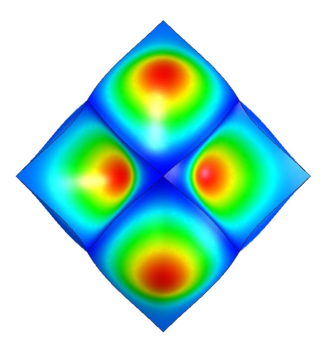
I re-ran the modal analysis with the new panel size of 4.124". I think I made a mistake on the thickness in my first scaling of the model because I got some pretty different numbers. I double checked, I'm much more confident in the new numbers (plus I re-ran the 4.25 and they are more in alignment with the new results now that I'm sure the model is correct). The first mode (back panels resonating) is 1476 Hz. Then 1529, 1541, and 1605. Sorry guys, but that peak appears to be a function of the modes of the box. If the box is radiating, analysis seems to indicate it's not broadband. Polar plots would be really great to see if this is what's happening.
I've attached the image of the first mode, looking straight at the back of the box (speaker panel is parallel to the screen, facing away), Colors indicate displacement of the model at the peak of movement. The rest of the box is blue.
Fascinating. I think it's safe to say that my 1.55khz observation is really 1.54khz - but why is that one so much more prominent than the others in my measurement? Also, at the risk of sounding naive, if something truly special is going on here, is it possible that there could be wide band panel resonance in real life that is not showing on the modesl?
BTW, I had a friend over to listen and he thought they sounded the same from the back and a little softer from the sides. --g
Here's a cross sectional view of the enclosure (cut right down the middle) showing what Matt is talking about in regards to the recommended construction method resulting in an edge at speaker baffle. Panels are all the same thickness. Drawings for each of the parts soon.
Attachments
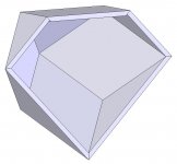
Here's a cross sectional view of the enclosure (cut right down the middle) showing what Matt is talking about in regards to the recommended construction method resulting in an edge at speaker baffle. Panels are all the same thickness. Drawings for each of the parts soon.
Can you model tell us what the internal volume is given an edge (the square baffle) of length S?
Either way, if anyone wants a 3D model part file, let me know. Should be a piece of cake to customize and export.
Mike
I was thinking for quite some time now to start a thread asking for useful info and general education over 3D printing for us the home diyers and your “piece of cake” offer worked like a catalyst in my mind.🙂
I opened this new thread, so you and anyone else versed into 3D printing will pay us a honor to write some lines there:
http://www.diyaudio.com/forums/everything-else/265201-3d-printing-diy-ing.html#post4128928
George
3D printing...
I don't sell em just love what they can do...Also love your software modelling very cool!
Over the next 3 to 5 years will see a major disruption in electronic assembly....
There are some amazing 3D machines out now....Its not going to be too long before we can design a loudspeaker driver & cabinet on our lap tops, email it to a printing house and they ship the finished item back....
The top current generation of 3D printers incorporate small pick and place machines so they can print "Printed Circuit Boards" using highly conductive graphene / carbon fibre thread for the tracks to replace solder
All Through the hole scale in 2015, but the 2016 / 2017 models will be capable of handling Surface mount size components ....
The possibilities are endless as we move towards molecular level assembly.....Its not quite Star Trek replicator but getting close within a decade!
Cheers
Derek.
Wow, that's really cool.
You don't sell these for a living do you? Because you're doing a pretty good job!
I don't sell em just love what they can do...Also love your software modelling very cool!
Over the next 3 to 5 years will see a major disruption in electronic assembly....
There are some amazing 3D machines out now....Its not going to be too long before we can design a loudspeaker driver & cabinet on our lap tops, email it to a printing house and they ship the finished item back....
The top current generation of 3D printers incorporate small pick and place machines so they can print "Printed Circuit Boards" using highly conductive graphene / carbon fibre thread for the tracks to replace solder
All Through the hole scale in 2015, but the 2016 / 2017 models will be capable of handling Surface mount size components ....
The possibilities are endless as we move towards molecular level assembly.....Its not quite Star Trek replicator but getting close within a decade!
Cheers
Derek.
... is it possible that there could be wide band panel resonance in real life that is not showing on the modesl?
YES! Always keep in mind that models are simply ideal representations. Especially modal analysis (it's really easy to be off in weight, stiffness, or configuration which would throw results way off). For instance, what if the glue holding the box together was flexing, allowing the enclosure to expand a little? That's why I suggested the polar measurements. They would help show us if what I'm predicting is true. Analysis should always be backed up with experimental results. If I had the resources, I'd build one of these and then stick an accelerometer on one of those back panels (and maybe a few other places) to get an idea of mode shapes. BTW, I can change materials if anyone wants some data on that. Not sure how to model wood...
XRK971, I'm using Solidworks and those are from the frequency analysis of Solidworks Simulation. I'm a mechanical engineer (and a bit of a jack-of-all-trades engineer). And yes, I can calculate internal volumes. I can either model the internal volume, or take a virtual mold of the inside and then ask Solidworks for volume of the part.
gpapag, I'll take a look and see if I can contribute.
I can get relative amplitudes of the modes from my analysis. At the 1529 and 1541 modes the amplitude is about 1.5 times what comes after. There's a good chance it's just larger because it's the first mode and it's overlapping with a different mode of similarly large relative size. These results make sense to me.Fascinating. I think it's safe to say that my 1.55khz observation is really 1.54khz - but why is that one so much more prominent than the others in my measurement?
Ok, here's a quicky drawing of the panels with a unit length of the square face. just scale to the right size.
How would one hold these panels together during glue curing? Looks like it might need a lot of tooling to get it right. I can imagine some 120° angle clamps, with some very careful alignment, but I'm not sure how well that would work.
Now, I better get to work.
How would one hold these panels together during glue curing? Looks like it might need a lot of tooling to get it right. I can imagine some 120° angle clamps, with some very careful alignment, but I'm not sure how well that would work.
Now, I better get to work.
Attachments
Well put Derek. The efficiency, (well, inefficiency) of the driver is intrinsic, but the output of the overall loudspeaker can be supplemented by cabinet panel resonance. I am well aware that this should be out of phase with the driver's frontwave since it is a dipole radiator, which is why most designs seek to minimize cabinet resonance. However, experience with this shape seems to suggest something different is going on for some reason. As greg noted, the perceived volume behind the unit seems only slightly less than in front. I realize this is merely anecdotal until polar plots are presented.
I'm not sure if I still have the measurement (I could always redo it) but the impulse response measurement from behind the enclosure showed a nice looking spike that was most definitely correct in terms of polarity (however, I think that was with the driver mounted with the magnet to the outside and reverse wired).
Not so fast grasshopper. People still want heavy and solid speakers. Heavy and solid means quality. Foamcore just won't cut it. I get the ***** and giggles when I show off the Cornucopyas. The expression on their faces is second to none for the builder, but they would never sell.It's all about finish. If you could find some way to finish foamcore in a creative an good looking way (washi paper for example) then surely you could sell these.
Not so fast grasshopper. People still want heavy and solid speakers. Heavy and solid means quality. Foamcore just won't cut it. I get the ***** and giggles when I show off the Cornucopyas. The expression on their faces is second to none for the builder, but they would never sell.
It depends on the intended market. Hifi enthusiasts like heavy, read, "quality" speakers. Young folks who move about dorm rooms etc like lightweight and mobility - and many may appreciate the green aspects of less material consumed in the production of such speakers.
Ok, here's a quicky drawing of the panels with a unit length of the square face. just scale to the right size.
How would one hold these panels together during glue curing? Looks like it might need a lot of tooling to get it right. I can imagine some 120° angle clamps, with some very careful alignment, but I'm not sure how well that would work.
Now, I better get to work.
That is why I use hot melt glue. Your hands are the clamps for 40 seconds until it sets. The joint is semi flexible so the geometry of the edges forces the final shape. It builds itself. You just need to attach the rhomboids and triangles in the correct order and orientation. Start with the square and glue the triangles to it like a flower petal. Then add the rhomboids between the petals one by one. The add the rhomboids that form the "tailcone". I glued the 4 rhomboids that form the tailcone by itself first then glued that to the front assembly.
It's "just" a matter of finding a snappy and quick way to explain why a light cab in this case is ok or even desirable. And if the price is according to the material cost and the Vifa or Faital drivers, these should sell like hot cakes if they look good enough and is sold with the right panache.
There is some unique properties to a light speaker. You can hang it from the ceiling in a single wire for example and maybe even put a led diode inside to create a lamp speaker if foamcore and paper is used.
There is some unique properties to a light speaker. You can hang it from the ceiling in a single wire for example and maybe even put a led diode inside to create a lamp speaker if foamcore and paper is used.
It's all about finish. If you could find some way to finish foamcore in a creative an good looking way (washi paper for example) then surely you could sell these.
Paint, Vinyl like they use for car 'graphix', Crayola Crayons, Wall paper, Fabric, Pasta (un-cooked), Lentils......
Endless possibilities, all you've got to do is use your imagination.
I still want to make these one day.
A Dodecahedron Speaker for Desktop Printers by seanmichaelragan - Thingiverse
A Dodecahedron Speaker for Desktop Printers by seanmichaelragan - Thingiverse
OK, so you guys may be right about light speakers. Heck people buy those little Bose things so...
If you are making it from wood, could you not use mostly wood glue but have a couple dots of hot glue along the joint as your clamp?That is why I use hot melt glue. Your hands are the clamps for 40 seconds until it sets.
Cal, are you suggesting to first apply wood glue, align the parts, then put a dot of hot glue (probably at the corners) to hold it together? Hot glue should come right off after the wood glue has cured. That's an interesting idea.
Cal, are you suggesting to first apply wood glue, align the parts, then put a dot of hot glue (probably at the corners) to hold it together? Hot glue should come right off after the wood glue has cured. That's an interesting idea.
That will be a mess as the wood glue will smear and drip all over the place as you fumble to hold it together. I think you tack with dots of hot melt and then use a hypo needle to inject wood glue into crevice between panels at the edges.
- Status
- Not open for further replies.
- Home
- Loudspeakers
- Full Range
- Hypercube Loudspeakers