3D scan & 3D print
Hi Tesserax,
I have been working with some students on 3D printing complex shapes (combining two different materials) and it looks like your Hypercube design is a perfect candidate for 3 D printing.
Rather than create dedicated software to calculate patterns in sheet materials to then be cut and joined to form your 3D shape you can simply (and at low cost) pop along to your nearest university engineering dept and ask them to do a 3D scan (internal & external) of one of your ready made polycarbonate Hypercubes.
The latest 3D printers are very fast, accurate and can work with a range of materials with high rigidity and low mass....Just what you need in this application.
Another advantage is that once the scan is complete its a simple matter to "size" the Hypercubes to any internal volume you require....Just enter the desired volume and the 3D map will alter to suit.
High quality 3D printers capable of printing objects up to 40 litres or so are now under $10K retail so well within the budget of most universities.
The manufacturing cost of each 3D printed Hypercube will be low, guestimate $25 for a 5 litre cabinet.
You could easily start small scale production with almost no money....
Partner with any business / educational dept with a commercial spin out division and a 3D printer and you are in business!!
All the best
Derek.
Indeed. Curious thing though -I'm not seeing that big sensitivity gain claimed for it. 😉
Yeah, I think most know that is impossible...however, if somehow the shape creates a virtual black hole that swallows the rear wave via some type of copasetic resonances....well at the very least they do look interesting. Will wait to see if XRK can tame the spike.
Overkill audio,
There is no need to 3d scan this shape as it is trivial to model in 3D with any CAD software. The basic shape is defined by unit edge on the square baffle and all other edges are sqrt(3)/2 of unit edge. One could make either by an assembly of 3D panels or by construction of unit cube with qnty 5 pyramids of unit base and height given by sqrt(5)/2. Then make a shell of defined thickness of the desired panel. Save as STL file and send file to any number of online 3d print shops (or university shops).
The foam core version costs less than $0.50 to make and 1hr. Can't beat that for a 4.6 liter cabinet that is almost infinite baffle.
Last edited:
As a sealed cabinet, one needs to know the volume of the Hypercube. I could fill it with rice or beans and measure volume approximately with a measuring cup. But.... since this seems to be a well understood mathematical geometry, lets do it based on geometric constructs. The rhombic dodecahedron is composed of a unit cube at its core with edge dimension a, and with six pyramids with square unit base edge a, and height h. Height of a pyramid is sqrt(5)/2. Volume of a pyramid with base a and height of a*sqrt(5)/2 is given by a^3*sqrt(5)/6. Volume of unit cube with edge a is given by a^3. Since we are truncating one pyramid off, total volume is a^3 + 5 x a^3*sqrt(5)/6 or total volume of Hypercube is given by:
Vhc =(1+5*sqrt(5)/6)*a^3
For a=4.62in, Vhc=282 cubic inches or 4.625 liters.
Vhc =(1+5*sqrt(5)/6)*a^3
For a=4.62in, Vhc=282 cubic inches or 4.625 liters.
Interesting analysis xrk971. I've always thought of it as (11/6)s^3 for overall volume where s is the side of the square. This is because if you fully truncate back to the face of the cube that the RD was derived from you have the equivalent of the 6 original pyramid components of the cube (inward-pointing pyramids made by the crossed internal diagonals of the cube and its faces) plus 5 more equal outward-pointing pyramids added to the faces of the original cube. Please let me know if I am wrong about this.
http://dogfeathers.com/mark/images/RHDODEC2.GIF
The precise internal volume, however, is a little trickier since you have to subtract the volume occupied by the wood, plastic, or foamcore. I am putting the finishing touches on a couple of ASP pages to enable easy calculation for anyone who is interested. Basically, I calculate the internal side of the square after beveling and then use (11/6)s^3 on that.
There is still some error in this method, of course, since my proposed method of construction from beveled pieces causes the square to have a wider bevel at 45 than the unbeveled but tilted at 45 degrees thickness of the long ends of the triangles. This means the inner surface of the beveled square intrudes into the interior a little.
Cabinet effects driver output
On the missing "increased efficiency" ....
It is not possible for a cabinet shape / material to increase or decrease the driver efficiency, that remains a pathetic 1% or less with typical full rangers.
But cabinets do have a very noticeable and measurable effect on driver output.
Looking at the comparison of driver cone surface area Vs external cabinet wall surface area is an interesting start.
Assume an average of Sd of a typical 7 to 8 inch full range driver at 200cm 2.
Now calculate the Sd of a 15 litre (internal volume) 12mm ply cabinet:
Assume cube shape for easy maths. 6 sides of 27.4cm by 27.4cm = 4,504cm2. Approx 22 times greater than the Sd of the driver....
So if the driver cone is moving plus / minus 1mm to generate an SPL of X dB, the (undamped) cabinet walls only need to be vibrating 0.045mm to produce an equivalent SPL....As this SPL will be out of phase and have a different frequency response there will be cancellation and reinforcement across the audible bandwidth.
This will be detected by measurement as well as audible.
Many loudspeakers designs try to eliminate the cabinet effects with the 100Kg "lead and rubber coffin" approach, others use lightweight cabinets as sounding boards, others go open baffle (still a sounding board unless you decouple the driver from the baffle) or no baffle...
The same driver(s) will sound very different in all the different cabinet designs....
The Hypercube will have its own sonic footprint and have an effect on the loudspeaker systems sound....No surprise and no rocket science required!
Returning to driver efficiency for a moment.
Over 99% of the electrical input energy of the amplifier is "wasted" or converted into heat via voice coil heating and frictional losses in the driver surround, suspension and of course mechanical vibration....
The total amount of energy going into the cabinet is far greater than sound energy emitted from the driver cone.....Its very easy to make the cabinet walls of our 15 litre cube vibrate 0.045mm with a 50 watt amplifier.....
20Kg sub woofers try to hop across the floor when a big class D amp sends them a bass line!!
All in good faith and food for thought.
Cheers
Derek.
Well put Derek. The efficiency, (well, inefficiency) of the driver is intrinsic, but the output of the overall loudspeaker can be supplemented by cabinet panel resonance. I am well aware that this should be out of phase with the driver's frontwave since it is a dipole radiator, which is why most designs seek to minimize cabinet resonance. However, experience with this shape seems to suggest something different is going on for some reason. As greg noted, the perceived volume behind the unit seems only slightly less than in front. I realize this is merely anecdotal until polar plots are presented.
Is commercial production still goal?
Tesserax,
Are you still hoping to produce these commercially?
My suggestions are all based on the best way to start low cost commercial production not DIY home brew....Foam board and hot melt glue is fine for XRK and the "here's one I made earlier look" but you cannot sell these!
Cheers
Derek.
Tesserax,
Are you still hoping to produce these commercially?
My suggestions are all based on the best way to start low cost commercial production not DIY home brew....Foam board and hot melt glue is fine for XRK and the "here's one I made earlier look" but you cannot sell these!
Cheers
Derek.
Durn. I botched the second image insertion. here it is

Hmm... I see your reasoning, I did not know that the pyramids that sit on the faces of the cube are same as the pyramids that are flipped inside to make up volume of cube, in which case 1/6 x S^3 is the correct volume, and 6+5 or 11/6 x S^3 is total volume.
Your formula will give for S=4.62in only 2.96 liters. Quite a difference from my equation.
Your image matches my geometrical reasoning: 1 cube of edge length S plus qnty 5 pyramids of base S and height given by S x sqrt(5)/2.
Vol of pyramid is S x S x height /3 = S^3 sqrt(5)/6
Vol of cube is S^3
Vol of 5 pyramids is 5 x sqrt(5)/6 x S^3
Maybe we don't agree on what height of external pyramid is?
If edge is S, then diagonal of cube face is S x sqrt(2) and midpoint edge is S x sqrt(2)/2.
If vertex edge of pyramid is S x sqrt(3)/2 then using Pythagorean theorem,
h^2 = edge^2 + half-diag^2
or
h^2 = [S x sqrt(3)/2]^2 + [S x sqrt(2)/2)]^2
h^2 = S^2 x 3/4 + S^2 x 2/4 = S^2 x 5/4
so
h = S x sqrt(5)/2
???
time to take out the dried rice and measuring cup 🙂
Last edited:
Tesserax,
Are you still hoping to produce these commercially?
My suggestions are all based on the best way to start low cost commercial production not DIY home brew....Foam board and hot melt glue is fine for XRK and the "here's one I made earlier look" but you cannot sell these!
Cheers
Derek.
Hollow cast aluminum with brushed anodized look would be very nice IMO. Foam may not look good but if idea is to re-radiate, it may be the best material given that NXT planar drivers use same material.
Tesserax,
Are you still hoping to produce these commercially?
My suggestions are all based on the best way to start low cost commercial production not DIY home brew....Foam board and hot melt glue is fine for XRK and the "here's one I made earlier look" but you cannot sell these!
Cheers
Derek.
It's all about finish. If you could find some way to finish foamcore in a creative an good looking way (washi paper for example) then surely you could sell these.
Key point is the phase....
Hi Tesserax,
To me the most exciting feature of your design is the possibility that you have found a way to make the cabinet radiation in phase not out of phase with the driver radiation!
If we assume your Hypercube does create a " virtual black hole" (VBH) behind the driver without any stuffing, dampening, viscoelastic materials etc it just might be doing something else rather special....
Allowing the rear wave of the driver to exit via the cabinet walls in phase with the main driver.....You are getting close to the ideal of a pulsating sphere which radiates equally 360 degrees into 3D space....Now that's cool!!
Normally the rear wave (which is of course equal in energy output to the front wave) bounces around inside the cabinet and re-emerges as delayed / out of phase "ghost echo's" via the driver cone. This is in addition to the vibrating cabinet walls radiating delayed / out of phase energy .....A mess!
The Hypercube might just be acting as one big driver, all be it with a very slight ghost echo ie the time it takes the rear sound wave to travel the 5cm, 10cm 15cm etc from the back of the cone to the various Hypercube cabinet walls.
The last point that springs to mind is that cabinet wall material will be vital / deal breaker....If and its a big if any of the above is actually occurring then the vastly different acoustic properties of polycarbonate and foam board will have a major effect on the end result....
I would guess that a thin light ridged polymer such as acrylic / polycarbonate or a custom OEM material will be the ideal....A floppy well damped foam / fibre board material will be the worst.....Very counter-intuitive to what conventional cabinet design dictates, but hey got to break some preconceptions to make an omelette!!
Cheers
Derek.
..... I am well aware that this should be out of phase with the driver's frontwave since it is a dipole radiator, which is why most designs seek to minimize cabinet resonance. .....
Hi Tesserax,
To me the most exciting feature of your design is the possibility that you have found a way to make the cabinet radiation in phase not out of phase with the driver radiation!
If we assume your Hypercube does create a " virtual black hole" (VBH) behind the driver without any stuffing, dampening, viscoelastic materials etc it just might be doing something else rather special....
Allowing the rear wave of the driver to exit via the cabinet walls in phase with the main driver.....You are getting close to the ideal of a pulsating sphere which radiates equally 360 degrees into 3D space....Now that's cool!!
Normally the rear wave (which is of course equal in energy output to the front wave) bounces around inside the cabinet and re-emerges as delayed / out of phase "ghost echo's" via the driver cone. This is in addition to the vibrating cabinet walls radiating delayed / out of phase energy .....A mess!
The Hypercube might just be acting as one big driver, all be it with a very slight ghost echo ie the time it takes the rear sound wave to travel the 5cm, 10cm 15cm etc from the back of the cone to the various Hypercube cabinet walls.
The last point that springs to mind is that cabinet wall material will be vital / deal breaker....If and its a big if any of the above is actually occurring then the vastly different acoustic properties of polycarbonate and foam board will have a major effect on the end result....
I would guess that a thin light ridged polymer such as acrylic / polycarbonate or a custom OEM material will be the ideal....A floppy well damped foam / fibre board material will be the worst.....Very counter-intuitive to what conventional cabinet design dictates, but hey got to break some preconceptions to make an omelette!!
Cheers
Derek.
Radiate not re-radiate!
NXT do not re-radiate anything....That's the whole point, they only radiate!
They use the entire baffle as a radiating area energised by multiple motor drivers or driver motors to be precise.
The outer surface is ridged and the inner layer is damped to minimise internal sound wave generation.
My guess ( hope!) is that the Hypercube is acting as a single pulsating sphere ( well multi sided asymmetric shape of debatable origin...!) which radiates with a very even broad band power response into 360 degree space.
I believe that the key is in developing the right cabinet material....Once you have your scan / 3d model you can very quickly print out dozens of different cabinet material options and examine the correlation between subjective sound quality and measured performance / technical spec of the materials used....That will be a fun and rewarding R&D process!
Cheers
Derek.
..... Foam may not look good but if idea is to re-radiate, it may be the best material given that NXT planar drivers use same material.
NXT do not re-radiate anything....That's the whole point, they only radiate!
They use the entire baffle as a radiating area energised by multiple motor drivers or driver motors to be precise.
The outer surface is ridged and the inner layer is damped to minimise internal sound wave generation.
My guess ( hope!) is that the Hypercube is acting as a single pulsating sphere ( well multi sided asymmetric shape of debatable origin...!) which radiates with a very even broad band power response into 360 degree space.
I believe that the key is in developing the right cabinet material....Once you have your scan / 3d model you can very quickly print out dozens of different cabinet material options and examine the correlation between subjective sound quality and measured performance / technical spec of the materials used....That will be a fun and rewarding R&D process!
Cheers
Derek.
Glad you like them, I'll try to get the rest done today (kinda doing this on small breaks at work). That mild peak at 3.4K could be the first mode at which the panels are resonating. The mode shape has the back four panels flapping like drums (I can post a pic if you're interested). So if a 360° polar plot was made, I would expect to see that the most in the back, probably slightly to the sides.MuddJester:
Wow. Thanks for your work. The thumbnails look great. Indeed, I observed a mild resonance at 3.4k and I suppose if dig deeper into the decay I'll find one at 4.4k as well.
Sorry to confuse you about the group buy thought. I'm just trying to provide some technical help for others to build these.
xrk971's enclosure looks great! That's amazing, I should pick up some of that foam board. Is that just from an art supply store?
And in case anyone is still confused about the shape I made a 3D PDF of my model with the shape solid (not hollow). It's attached. Comes up pink on my screen, I don't know why...
Attachments
Overkill,
I think xrk971 is right. No need to scan, took me 5 minutes to model this thing. Only reason I can think this design would not be scale-able is the need for a place for the speaker terminals. I don't think it would make sense, or be practical, to cut holes in a printed box.
BTW, are 3D printed panels air tight? I've seen a number of 3D printed parts, and it doesn't look like the material can guarantee air tight panels.
Either way, if anyone wants a 3D model part file, let me know. Should be a piece of cake to customize and export.
Asymmetry is your friend...
An effective technique to eliminate this type of resonance is to use different materials...Using several ( even a slightly different material for each side) different materials will eliminate the major peaks.
This is easy if DIY hand assembly, more complex but still ok with 3D printing.
Asymmetry is your friend in both cabinet shape and materials.
Cheers
Derek.
...... That mild peak at 3.4K could be the first mode at which the panels are resonating. ...
An effective technique to eliminate this type of resonance is to use different materials...Using several ( even a slightly different material for each side) different materials will eliminate the major peaks.
This is easy if DIY hand assembly, more complex but still ok with 3D printing.
Asymmetry is your friend in both cabinet shape and materials.
Cheers
Derek.
3D print with connection holes in the design
The 3D printer can print anything so just incorporate it in the design..
100% air tight is no problem.
The new printers can even incorporate other parts and materials.....
Want a threaded speaker mount in the base for stand or wall mount....
Want to include speaker cable sockets?
Want it sprayed any pantone colour?
All no problem.
From a commercial point of view 3D printing is a great way to go....By the time you have built and sold a few hundred pairs you will be able to buy your own machine and really start making good money.
Cheers
Derek.
....Only reason I can think this design would not be scale-able is the need for a place for the speaker terminals. I don't think it would make sense, or be practical, to cut holes in a printed box.
BTW, are 3D printed panels air tight? I've seen a number of 3D printed parts, and it doesn't look like the material can guarantee air tight panels.
.
The 3D printer can print anything so just incorporate it in the design..
100% air tight is no problem.
The new printers can even incorporate other parts and materials.....
Want a threaded speaker mount in the base for stand or wall mount....
Want to include speaker cable sockets?
Want it sprayed any pantone colour?
All no problem.
From a commercial point of view 3D printing is a great way to go....By the time you have built and sold a few hundred pairs you will be able to buy your own machine and really start making good money.
Cheers
Derek.
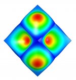
I re-ran the modal analysis with the new panel size of 4.124". I think I made a mistake on the thickness in my first scaling of the model because I got some pretty different numbers. I double checked, I'm much more confident in the new numbers (plus I re-ran the 4.25 and they are more in alignment with the new results now that I'm sure the model is correct). The first mode (back panels resonating) is 1476 Hz. Then 1529, 1541, and 1605. Sorry guys, but that peak appears to be a function of the modes of the box. If the box is radiating, analysis seems to indicate it's not broadband. Polar plots would be really great to see if this is what's happening.
I've attached the image of the first mode, looking straight at the back of the box (speaker panel is parallel to the screen, facing away), Colors indicate displacement of the model at the peak of movement. The rest of the box is blue.
I've attached the image of the first mode, looking straight at the back of the box (speaker panel is parallel to the screen, facing away), Colors indicate displacement of the model at the peak of movement. The rest of the box is blue.
Attachments
The 3D printer can print anything so just incorporate it in the design..
100% air tight is no problem.
The new printers can even incorporate other parts and materials.....
Want a threaded speaker mount in the base for stand or wall mount....
Want to include speaker cable sockets?
Want it sprayed any pantone colour?
All no problem.
From a commercial point of view 3D printing is a great way to go....By the time you have built and sold a few hundred pairs you will be able to buy your own machine and really start making good money.
Cheers
Derek.
Wow, that's really cool.
You don't sell these for a living do you? Because you're doing a pretty good job!
- Status
- Not open for further replies.
- Home
- Loudspeakers
- Full Range
- Hypercube Loudspeakers