Your new R2/R1 ratio is now 0.12
Maybe you meant to write that R2 is 1 ohm and R1 is 2.2 ohm ?
Class A will normally heat up more at idle without any sound at the output.
Thanks for the follow up, I’m waiting a little before ordering the components from Mouser.
Maybe you meant to write that R2 is 1 ohm and R1 is 2.2 ohm ?
Class A will normally heat up more at idle without any sound at the output.
Thanks for the follow up, I’m waiting a little before ordering the components from Mouser.


Regarding the attached gerber file, i haven't made any pcb order yet.
There may be some errors.
Possible.
There may be some errors.
Possible.
Hi,Your new R2/R1 ratio is now 0.12
Maybe you meant to write that R2 is 1 ohm and R1 is 2.2 ohm ?
Class A will normally heat up more at idle without any sound at the output.
Thanks for the follow up, I’m waiting a little before ordering the components from Mouser.
No mistake, I used 8.2 ohm R1, but because of the meagre bias current (about 150 mA), distortion sky rocketed. It became clear now - to me- that these TO247 mosfets are current hungry and they operate best at higher bias currents: with a 0.55 ohm R2 and an 1.2 ohm R1, measured current was about 0.7A, too much heat for me...but looking at your heatsinks, -- totally different story.
Bests
Last edited:
My final setup:
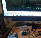
Laptop power supply 20.4V, R2=0.55ohm R1=1ohm. I also got back to Diego's original feedback resistor values: 330 ohm, respectively 2.2K. (This gain keeps THD at very low levels, with H2 distortion and the even ones ruling across the spectrum.
I'm overall very happy with this amplifier's sound, its measured performance and its tube-like harmonics shape.
According to the graphs below, THD at max power --1.8 W RMS -- is 0.54%; THD at 1W is 0.23%, THD at 0.5W is 0.14% and THD at 150 mW is 0.033%. I think these are really good figures for such a simple amplifier.
Thank you Diego and thank you guys for advice !
Attachments
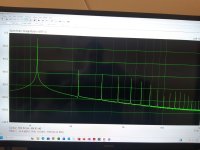

Looks good, especially your last pic, very smooth harmonic profile.
I’m about to order 5 PCB.
I’m about to order 5 PCB.
I managed to trim distortion even further by keeping the amps's nice H2 dominant shape.
THD=0.18% at 1W/1,100Hz.
THD is 0.11% at 0.5W and 0.3% at the max power of 1.8W RMS.
To accomplish this, I only increased 'a bit' the bias voltage ( measured between the positive side of C1 and ground) to 12.4V from 10.3V... this is not half my voltage supply of 20.4V anymore... should I worry about this ? How does this work ?Thanks,
Bests,
R
Hi
If you connect an oscilloscope at the output, is the clipping symmetric?
If you connect an oscilloscope at the output, is the clipping symmetric?
Only as a guide for those who wish to adapt it to their possibilities:
View attachment 1219134
Best regards
Check the last column for VCC voltages between 20 and 21 volts. The offset voltage should be close to 11 volts, for a VCC of 20.4 volts.
Anyway, the best option is to adjust with an oscilloscope to obtain asymmetric clipping, as already suggested adequately.
The offset voltage with respect to 0 volts is not the classic 1/2 VCC in this curious circuit.
Best regards
Where I said "asymmetric clipping", it should be "symmetric clipping" 😉
Weird finding:
Clipping occurs only at an offset voltage of 9.3V at the bottom of the sine and at 13.5 V at its top, so over almost the entire range of the pot, the sine wave doesn't change its shape nor its amplitude. Please note this measurement was done at max power (Vrms=3.8V, Vpp=10.7V).
Clipping occurs only at an offset voltage of 9.3V at the bottom of the sine and at 13.5 V at its top, so over almost the entire range of the pot, the sine wave doesn't change its shape nor its amplitude. Please note this measurement was done at max power (Vrms=3.8V, Vpp=10.7V).
My fault...I injected a larger signal into the amp and that has made it a lot easier to visualise the clipping and find the 'middle spot'.
Thank you Diego, I eventually found out that an offset voltage of 11.2V was the best compromise for my setup.
Thank you Diego, I eventually found out that an offset voltage of 11.2V was the best compromise for my setup.
I would like to make a fair comparison between Diego's simple class A, single ended amplifier and, let's say, any other class, more complex amplifier.
Have you ever been going up/down in a narrow, old elevator in a 15-storey bloc of flats? I've been, many times. I know how it is.
Have you ever been in an open bird cage-style elevator made of wrought-iron grillwork going up? or going down ?
Have you ever been going up/down in a narrow, old elevator in a 15-storey bloc of flats? I've been, many times. I know how it is.
Have you ever been in an open bird cage-style elevator made of wrought-iron grillwork going up? or going down ?
Should we understand that Diego’s amp is airy and good imaging? I’m not certain I understand your elevator’s comparaison.
Yes, maybe my comparison is not the best one describing this amp. But, indeed, you're right: this little thing produces an airy and natural sound.
Comparison test sound:
Single ended with LM317:
Comercial LG Amplifier LH-D6245A:
In a humble comparison filmed from a cell phone, using the same speaker and signal source, I found a pleasant preference for the amplifier in this same thread, in contrast to a commercial LG brand one (set to flat equalization).
- Home
- Amplifiers
- Pass Labs
- Hybrid ZEN Amplifier + LM317 = Efficient and simple