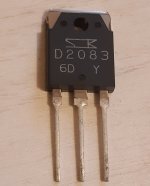
I also tried this heavyweight, a Sanken Darlington, 120 Watt transistor. It works flawlessly. But, as any other TO247 transistor it likes larger current. So, R2/R1 of 1ohm/1ohm, 0.82ohm/0.82ohm, or 0.68ohm/0.68ohm (916 mA quiescent current) fits it.
Attachments
Keep in mind that if you use a 1.5 A maximum current regulator (usually in a TO-220 package), the quiescent current should not exceed 750 mA (for R1 = R2), so that at the maximum expected signal peaks before clipping, the current reaches a worst-case maximum of 1.5 A.
There would be an exception to using higher quiescent currents if you keep the excursion below what the power supply allows. For 8-ohm loads, this would be about 12 Vp (or 24 Vpp) for a 1.5 A regulator (even if the power supply allows more than 12 Vp or 24 Vpp)
There would be an exception to using higher quiescent currents if you keep the excursion below what the power supply allows. For 8-ohm loads, this would be about 12 Vp (or 24 Vpp) for a 1.5 A regulator (even if the power supply allows more than 12 Vp or 24 Vpp)

A speaker is never constant resistive.
Calculating maximum current using 8R is just a guide line.
I would always want to have sufficient reserve when the load is reactive and can also dip below the nominal value.
On top of that, a TO220 has limited dissipation capability.
So for high power version, I would use at least 3x LM317 (-HV if >37V) in parallel, or LM338 (limited to 40V) with good thermal contact to the heat sink.
And of course cascoding the regulators have also been discussed before.
Last thing I would want is for the internal protection to cut in because of excessive dissipation.
Maximum rating in datasheets are exactly that. It is not meant to be for continuous operation. Certainly not for high reliability.
My 2 cents,
Patrick
Last edited:
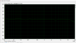
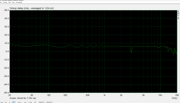
Thank you for your advice. I tried, sort of, using an 8.2 ohm dummy load resistor make use of Arta software to get smoothed frequency response of my amp. I got these graphs - 1/3 and 1/24 smoothed group delay. How do they look ? Many thanks!
Attachments
Does the measured frequency response correspond to a Darlington transistor?
Although I haven't used ARTA in a while, it seems the vertical axis doesn't correspond to dB gain units. Doesn't it indicate Group Delay?
I'd like to thank you for your effort in measuring it and your enthusiasm for the circuit.
I also want to give special thanks for Patrick's more precise and extensive explanation regarding quiescent current. As he said, what I pointed out was for guidance only.
Thank you Diego, Patrick for your guidance and patience. I really like this special circuit. Indeed the graphs above stem from testing the Sanken Darlington, and indeed they show the Group Delay smoothed 1/3 octave and 1/24 octave.