If you already sold some PCB or sold some Gerbers, your buyer can simply put a piece of wire instead of your 220 ohm. Easy fix.

Julian, the 220R placement in the updated schematic doesn’t match the pcb layout.
Looks like the trimpot wiper is connected between the 4u7 cap and 220R on the pcb.
Looks like the trimpot wiper is connected between the 4u7 cap and 220R on the pcb.
Easy fix.can simply put a piece of wire instead of your 220 ohm. Easy fix.
Yes, it's a small design error. It can be done as specified.
Now I've seen it...
Others have probably seen it before but haven't said anything.
Maybe, I am wrong but gate stopper resistors are always "in series with the gate."
So: Pot wiper goes to one end of the 220 ohm resistor. The other end of the 220 ohm resistor goes straight to the gate, and very close to it. Then the 4.7uF capacitor goes to the wiper: like in pix attached.
So: Pot wiper goes to one end of the 220 ohm resistor. The other end of the 220 ohm resistor goes straight to the gate, and very close to it. Then the 4.7uF capacitor goes to the wiper: like in pix attached.
Maybe, I am wrong but gate stopper resistors are always "in series with the gate."
So: Pot wiper goes to one end of the 220 ohm resistor. The other end of the 220 ohm resistor goes straight to the gate, and very close to it. Then the 4.7uF capacitor goes to the wiper: like in pix attached.
Attachments

Hi Diego,
You didn’t include a gate resistor for the IRFP150 in your original schematic, is this 220R resistor needed?
You didn’t include a gate resistor for the IRFP150 in your original schematic, is this 220R resistor needed?
It is always a good idea to have a gate stopper.
As close to the gate pin as possible.
Patrick
As close to the gate pin as possible.
Patrick

such a difference - maybe HF oscillation (can be in the range above what a scope sees)? Try a larger stopper and one without/with less inductance . . .IRF630 case temperature measured with infrared thermometer is about 48 degrees after half an hour at max power. IRFP 044 case temp under same conditions has reached about 55. Does not make much sense but this is what the thermo says.
Hi Diego,
You didn’t include a gate resistor for the IRFP150 in your original schematic, is this 220R resistor needed?
I haven't included it in my tests. While I haven't had any issues, it's good practice to include it as close to the gate terminal as possible, as Patrick correctly suggested.
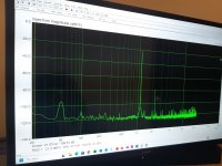
Hi and thank you. Oscope shows very clean sine waves from about 7 Hz until around 19 Khz.such a difference - maybe HF oscillation (can be in the range above what a scope sees)? Try a larger stopper and one without/with less inductance . . .
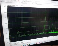
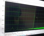
Some Arta measurements: at lowest power, amp has 0.078 THD, almost all H2. At max power, 3.2W RMS, distortion is 1.8%.
Overall I am very happy with this amplifier's performance (meaning sound), as H2 distortion 'rules' across the whole spectrum.
P.s- My Wien bridge signal generator alone has 0.0028 % THD and outputs 1100 Hz.
Thank you Diego !
Overall I am very happy with this amplifier's performance (meaning sound), as H2 distortion 'rules' across the whole spectrum.
P.s- My Wien bridge signal generator alone has 0.0028 % THD and outputs 1100 Hz.
Thank you Diego !
Attachments

- Home
- Amplifiers
- Pass Labs
- Hybrid ZEN Amplifier + LM317 = Efficient and simple