I share a simple guideline table (elaborated from simulation) for those who wish to adapt the scheme of the first post to different voltage gain needs. It states that one of the resistors of the feedback loop remains unchanged (R6), while different values are given for R5. For each value of R5, we will have different voltage gains, the upper cut-off frequency of the circuit will also change and the distortion will be altered somewhat and possibly its profile somewhat (all these parameters should be properly checked under real operating conditions). In the table we can compare the total distortion at 1 W over 8 ohms and 1 KHz, for different preset gains, to compare similar operating conditions on the load.

Best regards
Best regards

This is really helpful, many thanks for computing this. Maybe I should aim for the lowest possible distortion, which implies a 470 ohm R5, and then use an almost 'distortionless' LM4562 simple preamplifier, to output at least the tequired 2 volt RMS for 1watt... think this approach might be desirable than boosting the amplifier's internal gain instead. Maybe I am wrong, but as you said previously, some more H2 distortion could be nice.I share a simple guideline table (elaborated from simulation) for those who wish to adapt the scheme of the first post to different voltage gain needs. It states that one of the resistors of the feedback loop remains unchanged (R6), while different values are given for R5. For each value of R5, we will have different voltage gains, the upper cut-off frequency of the circuit will also change and the distortion will be altered somewhat and possibly its profile somewhat (all these parameters should be properly checked under real operating conditions). In the table we can compare the total distortion at 1 W over 8 ohms and 1 KHz, for different preset gains, to compare similar operating conditions on the load.
View attachment 1421269
Best regards
Bests,
Radu
It is likely that the R5 value that you have initially chosen (3K3) will work more in your favor in terms of the interaction with the acoustic distortion that occurs in the speaker (possibly reducing it somewhat in the range of 40 to 300 Hz, mainly). It is very likely that outside this range you will not detect noticeable changes in terms of acoustic distortion reduction.
Everything is possible to try, you just have to measure it with the appropriate instruments (microphone + REW, for example). Also, don't stop relying on what your ears can perceive, which also count.
Keep in mind that adding stages and how they spectrally alter the distortion components together with the amplifier could imply a modification in the final electrical distortion profile that no longer works in our favor in terms of a possible reduction in acoustic distortion. Maintaining some H2 and a lesser amount of H3 could be favorable to a certain extent. The phases of the spectral components of each of the stages that are added to the chain come into play.
All the best.
Thank you for your detailed explanation, I've never looked at it this way. I will post THD measurements with ARTA, as soon as possible. I'm almost done with making an ultra-low 1KHz signal generator, THD of 0.002 and a proper sound card.
Bests
Bests
...a Wien bridge signal generator based on a tiny light bulb and on LT1037 opamp.
This is the culprit. It measures excellent THD, I only need to put it in a small box.

See. I uploaded the Qspice schema file. The LM317 model is already built into it.

Attachments
Last edited:
I still have two sets available. I'll give them together to whoever wants them.
15 EUR including shipping.
15 EUR including shipping.
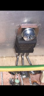
I replaced the IRFP044 with a TO220 body IRF630 (this has a much lower input capacitance).
The result? Same output voltage RMS, heatsink about 5÷7 Celsius below the TO247 Mosfet (at almost full power for 30 minutes), and most importantly, 'more' natural sound, crispier.
I cannot explain all these above, but this is what I could hear.
The result? Same output voltage RMS, heatsink about 5÷7 Celsius below the TO247 Mosfet (at almost full power for 30 minutes), and most importantly, 'more' natural sound, crispier.
I cannot explain all these above, but this is what I could hear.
Attachments
here are some alternatives with less Rdson and nearly the same/better ciss. Transcundactance is also fine

kr
chris
kr
chris
Thank you, from the list I only had/tried, an IRF520 (isolated, plastic body) but it burst into flames when I put max power into it.
Bests,
Radu
Bests,
Radu
That probably translates into a higher case and junction temperature.heatsink about 5÷7 Celsius below the TO247 Mosfet
IRF630 case temperature measured with infrared thermometer is about 48 degrees after half an hour at max power. IRFP 044 case temp under same conditions has reached about 55. Does not make much sense but this is what the thermo says.
I didn't measure current, my ammeter is dead. On oscilloscope, on the same 8 ohm load and using same sine wave 1KHz signal, there's same 5 volt RMS output, irrespective of mosfet used: IRFP044 or IRF630.
Same current?
Almost independently of the mosfet chosen, the current that circulates through the drain changes very marginally, to the point of being able to consider that they will operate at practically the same value of quiescent current.
I replaced the IRFP044 with a TO220 body IRF630 (this has a much lower input capacitance).
The result? Same output voltage RMS, heatsink about 5÷7 Celsius below the TO247 Mosfet (at almost full power for 30 minutes), and most importantly, 'more' natural sound, crispier.
I cannot explain all these above, but this is what I could hear.
In an extremely simple circuit like the one in this same thread, it is very likely that the perceived and measurable changes will be in an extension of the high frequency response (more noticeable with certain models of mosfets than others). Mainly, due to differences between the parasitic capacitances formed between the electrodes of the mosfet.
To a much lesser extent or almost no extent, an alteration in the passband gain, distortion and its respective distortion profile could be detected by measurements.
What will not be significantly altered is the amplifier's lower cutoff frequency.
All of this will be open testing that builders can experiment with as they wish.
Best regards
Last edited:
- Home
- Amplifiers
- Pass Labs
- Hybrid ZEN Amplifier + LM317 = Efficient and simple