I'm very glad you built it and can enjoy it. It is very likely that changing R5, in addition to increasing the voltage gain, will reduce the high frequency response somewhat (although only measurement or a simulation with accurate models will indicate the amount) and increase the THD somewhat. In any case, it is likely that the high frequency limitation falls well outside the audible range and the increase in distortion acts in favor depending on the speaker used (due to the statistical probability of a minimization of acoustic distortion with the consequent greater electrical distortion generated in the amplifier itself and the respective phase of certain spectral components in the distortion profile).
Would you be able to measure input signal levels to the amplifier and typical output signal quality parameters with a program such as REW, ARTA, DAQARTA, etc.?
From the description of the natural sound that you mention, it is likely that the electrical distortion thus achieved in the amplifier (with the increase of R5) is favoring your configuration of signal source + amplifier + speaker + environment + listener, in terms of acoustic distortion, which is what we finally hear.
Many thanks to you !

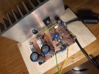
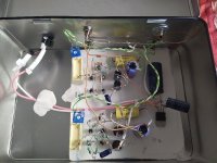
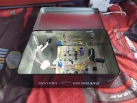
I am not skilled at all in designing PCBs, the prototype was built as seen in the videos and I still have it built like that (my laziness is strong). I only focus on enjoying my constructions in terms of their operating parameters (not their constructive beauty). I wish I had the skill and patience of many here who build true beauties of circuits.
Best regards
Best regards
Diego, many thanks for your very detailed answer. I use a full range 30W, 13cm, paper dual cone Monacor speaker in a homebrew, 25x35cm wooden OB. I have ARTA but it would take a couple of days to make a proper setup for all measurements. What I've done so far, on my handheld oscilloscope I can clearly see a clean sine wave amp ouput, with input provided by an online generator using my mobile phone, at 5 Hz, 100 Hz, 1000 Hz, 10KHz, 18Khz. Max input RMS is about 0.4V and output RMS is around 3.7V (measured on the amp output's 5W, 8.2ohm resistor)--clean looking sine wave.
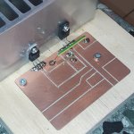
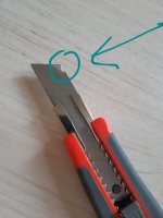
Ref PCBs, I always use this quick enough technique for them, scratching copper clad with this cutting tool.
Bests,
Radu
Ref PCBs, I always use this quick enough technique for them, scratching copper clad with this cutting tool.
Bests,
Radu
Attachments
Don't be so lazy. 😊For Patricks version with 3x LM317HV.......no
Patrick
Patrick alsways give you a smal hint...
Translation...
Point to point and you are finished!!!!!😛
Translation...
Point to point and you are finished!!!!!😛
I would agree that it would be easier with a PCB if you would build post #111.
But then I am sure you can make your own with KiCad etc.
PS The disclaimer still applies.
Patrick
But then I am sure you can make your own with KiCad etc.
PS The disclaimer still applies.
Patrick
Was there gerbers for a pcb layout for this amp shared here?


Hi Vunce,
I’ve made a PCB but haven’t built it yet.


Attachments
Last edited:
Hi RaduHi,
I used IRFP044 instead of Diego's IRFP150, and because I've used a low output portable CD player as a source, I increased feedback resistor R5 to 6.6K from 2.2K. I mention I use a laptop smps which outputs 20.4V, and 5Watt resistors R2=1ohm and R1=1.2ohm. If it's possible, Diego, please help me: how my feedback resistor change (giving larger voltage gain) impact THD ?
Many thanks !
Nice build
Both your transistors look like the size of TO-220. The IRFP044 is usually manufactured as TO-247 which is much bigger than TO-220. Could you please verify your transistors. I’m just waking up with my first coffee so hope I’m not saying vlakies.
Thanks
Eric
I would agree that it would be easier with a PCB if you would build post #111.
Again, referring to #111 for the LU1014 version.
The circuit has such similarity to Zen V9, that you can modify a Zen V9 PCB design to suit.
Here is one good example (just use Google translate) :
http://domainedupossible.free.fr/pagemus/ZENV9/zenv9.htm
http://domainedupossible.free.fr/pagemus/ZENV9/implantation ZV9.pdf
http://domainedupossible.free.fr/pagemus/ZENV9/pcbZV9.pdf
Patrick
What is a PCB?... it would be easier with a PCB....

Attachments


Sweet!Hi Vunce,
I’ve made a PCB but haven’t built it yet.

I like the tweaks you included to the circuit, thanks for sharing Eric.
I am also interested in the parallel trio of LM317's fed with a 48V supply and increased bias current as Patrick suggested.
Mo Powa to drive my speakers
 .
.Why not use a single 1084 with cascode.
The 1084 does not need much voltage headroom.
Neither does the 240.
Patrick
The 1084 does not need much voltage headroom.
Neither does the 240.
Patrick
- Home
- Amplifiers
- Pass Labs
- Hybrid ZEN Amplifier + LM317 = Efficient and simple