This neat little amp looks like it would also work well with the IRFP048, a close descendant of the IRF044 as used in the original Zen amps.
The original. 😎
As already mentioned in post #4, you can consider using 4x LM317HV in parallel to enable higher rail voltage.
Patrick
.
Attachments
Last edited:

Although I present it as an open concept, what could be added to arrive at a fixed design would be a decoupling capacitor at the input of the regulator (very close to it) and a 1N4007 type diode between the input and output pins of the regulator itself (cathode on the output pin of the regulator and anode on the input pin of the regulator), both elements that have not been incorporated for reasons of clarity of the initial diagram. That would be, at most, since it is a terribly simple scheme and I don't think it supports much more than what it already is, unless it is necessary to mount a version with much more power (several LMs and several Mosfets).
Best regards
Best regards
(cathode on the output pin of the regulator and anode on the input pin of the regulator)
I think the cathode at the input and the anode at the output is more correct.
The purpose of a diode present from the output to the input of the LM317 is to provide a discharge path that protects the regulator from reverse current in the event of a rapid collapse of input voltage relative to output voltage.
In the application proposed here, the input and output voltages around the regulator are likely to discharge with similar rate, or more likely to have the output voltage discharge faster through the speaker terminals or local load resistor. The diode may not be necessary, but if one is used, it should be of the 1N400x series as noted above.
In the application proposed here, the input and output voltages around the regulator are likely to discharge with similar rate, or more likely to have the output voltage discharge faster through the speaker terminals or local load resistor. The diode may not be necessary, but if one is used, it should be of the 1N400x series as noted above.
For the expense of one 1N400x, I would always play safe.
🤓
Patrick
🤓
Patrick
I think the cathode at the input and the anode at the output is more correct.
View attachment 1233126
I apologize for my mistake. Although I was thinking precisely about that diode (D1) and that this is how it should be connected (as the manufacturer suggests), I did the opposite 🤣🤣🤣.
Sorry once again.
Anyway, you will understand what I meant. There isn't much science behind that.
Best regards
Don't forget to invert polarity of your speakers.
I didn't see it mentioned in text, but on the schematics in post #1.
It is an inverting amplifier.
Hopefully Diego will tell you whether the H2 is negative phase or not.
🤓
Patrick
I didn't see it mentioned in text, but on the schematics in post #1.
It is an inverting amplifier.
Hopefully Diego will tell you whether the H2 is negative phase or not.
🤓
Patrick
Just to clarify, I was meaning TO3P devices for the amplifier PCBs, pretty sure the pin outs of LM317 and LT1084 are the same.
See post #2. LM1084, LD1084 are all copies of the original LT1084, but cost less.
Not sure whether they also "sound" the same.
But all are limited to 30V, hence the alternative solution to use 3~4x LM317HV in parallel instead.
Matches perfectly with the 60V of the IRFP044.
As in all First Watt amps, 48V single rail at 1.3A bias will let you swing +/-20V into 8 ohm.
And each TO220 only dissipates 8~10W.
Or 24~30°C rise junction to case.
Patrick
Since we are at it, why not replace the MOSFET with the LU1014 triode cell as in F3 ?
Will simplify the input biasing circuit and removes the input coupling cap.
I am pretty sure many people are ready to supply matched LU 1014s. 🤓
https://www.diyaudio.com/community/threads/f3-as-headphoneamp.405381/#post-7504556
Patrick
Will simplify the input biasing circuit and removes the input coupling cap.
I am pretty sure many people are ready to supply matched LU 1014s. 🤓
https://www.diyaudio.com/community/threads/f3-as-headphoneamp.405381/#post-7504556
Patrick
Last edited:
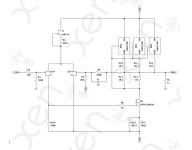
Something like this. 🤓

Disclaimer :
Not built, not simulated. So build at own risk.
The output should always have some load, say 100R // speaker.
Patrick
Disclaimer :
Not built, not simulated. So build at own risk.
The output should always have some load, say 100R // speaker.
Patrick
Last edited:
But if we cascode anyhow, we can also cascode the LD1084, right ?
Yes, we can. 🤓

Same disclaimer as above.
Patrick
Yes, we can. 🤓
Same disclaimer as above.
Patrick
Yes, cascoding the LD1084 (or LM1084) is standard practice for operating in higher voltage applications. The Zener diode D2 in the above diagram is essential to protect the regulator, as D1 protects the LU1014.
This is starting to look like something fun to try with larger speakers.
This is starting to look like something fun to try with larger speakers.
🙂
The top cascode serves 2 purposes.
It not only allows much higher voltage swing.
But equally important, it takes the bulk of the dissipation away from the TO220 device.
In Diego's circuit, the bias current is determined by the LM317 and associated resistors.
In the LU1014 circuit, the power JFET determines the bias.
(See article on Zen Variation 9)
https://www.passdiy.com/gallery/amplifiers/zen-variations-9
Hence TR13 is added to allow easy adjustment of the bias current of the LD1084.
Patrick
Hi
Back to the OP design.
According to their spec sheet the LM317T is rated at 40V, 1.5A but what about trying the LM338T, also rated at 40V but 5A instead of 1.5A 👍
If someone can confirmed that the LM338 would work I’d definitely used that one.
Thanks
Eric
Back to the OP design.
According to their spec sheet the LM317T is rated at 40V, 1.5A but what about trying the LM338T, also rated at 40V but 5A instead of 1.5A 👍
If someone can confirmed that the LM338 would work I’d definitely used that one.
Thanks
Eric
Replacing the LM317T with the LM338T would be an interesting route to explore, maintaining the circuit simplicity with which the thread originated, with which the reliability offered by the small number of components can also be maintained.
I do not detract from the alternatives kindly presented by EUVL, which probably perform better than the option that starts this thread. In that case, it would be interesting to differentiate these variants in a specific thread, so that forum members are not confused when building a variant.
Best regards
Quite the contrary, Patrick, the latest scheme you have kindly uploaded is more than promising. It is likely to offer a more extended frequency response when using this technique (cascoding).
It would be great if you built it and let us know how it goes.
Diego
It would be great if you built it and let us know how it goes.
Diego
Last edited:
I don't build amps with output coupling caps.
So some brave soul would have to take it up, I am afraid.
🙂
Patrick
So some brave soul would have to take it up, I am afraid.
🙂
Patrick
I don’t also see a problem with hijacking when you offer such valuable info.Sorry for hijacking.
And 338 is good choice.
Patrick
I just mentioned to go back to the original design because I’ve created my own PCB.
Eric
We are misusing these 3-pin regulators here, as they are normally not called upon to deliver a dynamic current up to 20 kHz.
So apart from static current rating and dissipation, their dynamic response is of great importance.
There are no published data available, so one would have to test in circuit.
Many examples exist for using LM317 as amplifier.
But at least there is one example for the LM338 :
https://www.electronicsforu.com/electronics-projects/voltage-regulator-audio-amplifier-2
Patrick
- Home
- Amplifiers
- Pass Labs
- Hybrid ZEN Amplifier + LM317 = Efficient and simple