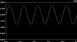
What tubes will handle 2 or better yet 3 kV with good performance at audio frequencies, and have good power (at least tens of watts)?
572B/T160L. If you just need the AC part and don't need to have enough offset to swing to 3kV, you could get by with an 811- it's good for 2-2.5kV swing, peak to peak.
What about the 833a ? This cheap (~100 $US) DHT is good
for about 40w single ended. But if you only need 20 watts you
might run it at a little less than the recomended 10v ,10a cathode current to extend tube life,it might even sound better....
for about 40w single ended. But if you only need 20 watts you
might run it at a little less than the recomended 10v ,10a cathode current to extend tube life,it might even sound better....
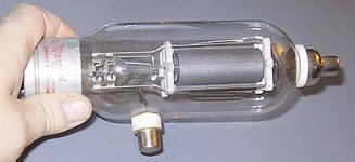
I may try to find some of those Eimac ceramic power tubes used somewhere. It'll be fun figuring out how to do the forced air cooling 
Actually, the graph I posted above is mistaken, as I need current output...
40W are not enough, as only a fraction of the tube's output will be audio; this is biased a lot as the average power goes into maintaining the plasma; essentially it is a current source modulated by audio.
Actually, the graph I posted above is mistaken, as I need current output...
40W are not enough, as only a fraction of the tube's output will be audio; this is biased a lot as the average power goes into maintaining the plasma; essentially it is a current source modulated by audio.
810
The 810 should do the job nicely. This is like an 805 on steroids and has a grid cap on the side as well as a plate cap on the top. Graphite plate good for 175 watts PD and 2500 volts on the plate is the CCS DC rating IIRC.
As suggested earlier the 833A would also work but would be a huge overkill for your application needs. With 450 watts of PD it can procuce ~120 watts in SE, not just 40.
Never starve the filament of a thoriated tungsten power tube as this will not lengthen tube life but rather shorten it! The RCA transmitting tube manual, and they ought to know, is very specific on the importance of proper filament voltage for such tubes. Starved filament operation, something thought up somewhat recently by audio experimenters is a technique best left only to low power, signal path tubes when using DH cathodes. It's purpose here is not longer tube life but reduced distortion and noise.
So will these tubes work well for single ended class A transconductance amplifier? I'm driving plasma, and the load in a SPICE sim essentially behaves as two antiparallel zeners in series, with 2-3 kV breakdown voltage.
One more question. I've been looking at the Eimac 3CX800A7 because it uses beam forming to shoot the electrons between the grid wires, and gets improved IMD figures according to a site I came across. However, the tests were for RF, and I'm wondering if this would also show improvements at AF. Another thing is, I read a comment (http://www.eham.net/reviews/detail/2933) that the Svetlana 4CX800A is a substitute, and much cheaper instead of the $400+ Eimac focused cathode tube. However, I wonder if how close the distortion performance would be. And when it says on Eimac's site that it's designed for class B, does that mean that it will merely not be as efficient in class A, or blow up or what?
One more question. I've been looking at the Eimac 3CX800A7 because it uses beam forming to shoot the electrons between the grid wires, and gets improved IMD figures according to a site I came across. However, the tests were for RF, and I'm wondering if this would also show improvements at AF. Another thing is, I read a comment (http://www.eham.net/reviews/detail/2933) that the Svetlana 4CX800A is a substitute, and much cheaper instead of the $400+ Eimac focused cathode tube. However, I wonder if how close the distortion performance would be. And when it says on Eimac's site that it's designed for class B, does that mean that it will merely not be as efficient in class A, or blow up or what?
I'm not sure what you are trying to do, but that load, both the plasma and the zeners, sounds to me like an awfully low load impedance. Could you perhaps post a circuit, please?Prune said:So will these tubes work well for single ended class A transconductance amplifier? I'm driving plasma, and the load in a SPICE sim essentially behaves as two antiparallel zeners in series, with 2-3 kV breakdown voltage.
I will have to pass here, I have never attempted to use these tube types for anything resembling audio, nor do I recall seeing datasheets specifying operating parameters for class A, audio or otherwise.One more question. I've been looking at the Eimac 3CX800A7 because it uses beam forming to shoot the electrons between the grid wires, and gets improved IMD figures according to a site I came across. However, the tests were for RF, and I'm wondering if this would also show improvements at AF.
Either may blow up if you try to run them in class A, but not for the reasons you may expect.Another thing is, I read a comment (http://www.eham.net/reviews/detail/2933) that the Svetlana 4CX800A is a substitute, and much cheaper instead of the $400+ Eimac focused cathode tube. However, I wonder if how close the distortion performance would be. And when it says on Eimac's site that it's designed for class B, does that mean that it will merely not be as efficient in class A, or blow up or what?
The Svetlana 4CX800A, a tetrode, is not a direct substitute for the Eimac 3CX800A7, a triode. They will not even fit the same socket. They are only replacements insofar as each, given the right operating parameters, can provide around 16dB of amplification at a power output of around 800W of RF (class AB).
In your shoes I might not attempt to work with these ceramic power tubes in the first place, they are cranky beasts to say the least.
First, due to their fairly high maximum frequency of operation of several hundred MHz, they are quite prone to parasitic oscillations. They are not suitable for breadboarding and kitchen desktop operation. You definitely need the proper socket for the type in question, the one made by the manufacturer with a screen bypass capacitor good to well into the UHF region built in. Also your physical layout needs to provide adequate isolation between the grid and the anode circuit, even more so if you make an audio circuit with unknown parasitic resornances in the 100-300MHz region.
If you do get a parasitic oscillation, you should count yourself lucky if you only burn out the grids in the tube, these are made from a very fine wire mesh. If unlucky, then something will blow up, literally. 😱
Secondly cooling these monsters is not as easy as that. Finding a centrifugal blower, which can provide adequate air volume at the needed back pressure, is not easy, and in particularly not noiseless if you want to continuously dissipate close to the maximum allowed on the anode. A friend of mine use a large 2' welding ventilation blower for cooling an amp I designed, though that was for a cheramic Eimac tube, which is just 'slightly' larger than the 3CX800A7. 😀
For the cooling noise alone I would not use this type of tube in a Hi-Fi project in an otherwise quiet room.

I would perhaps look into one of the radiation cooled graphite anode/glass envelope transmitting type triodes or tetrodes, like the 4-125, 3-500Z or the 4-250. Run one (or a pair) below maximum dissipation, and you may get away with using a simple, low velocity fan or two to cool the tube envelope and the socket pins. With high quality fans that could be made nearly noiseless.
Side benefits: They are specified for audio use if memory serves. Additionally they are very rugged tubes for the experimenter with grids made to be run literally at white hot temperatures. They are nearly indestructible and looks cool (actually, hot!) to boot. 16 or 17 years ago I built and ran a 300W+ amp for the 28MHz amateur band using a single 4-250 @ 2.8KV in ground grid configuration. A friend of mine still uses that amp with the original tube in place.
Frank.
I just got this reply at rec.radio.amateur.homebrew:
"The 3CX800A7 has been used sucessfully in class-A single-ended audiophile amps for a while now."
Funny, I didn't come across any during my Googling.
Anyway, you can see the I-V characteristics of my load in the attachment. It will be in the region F-H. Sound compression wave generated is approximately proportional to Power input, but in the F-G region this means essentially current input. Class A is efficient driving this since the bias goes towards maintaining plasma power and is not wasted. This is single ended since the rarefaction wave depends on the thermal relaxation constant of the plasma and not the amplifier.
What I said about the zeners is because I have seen region F-G simulated in SPICE using zeners.
I don't know whether I'm going to have an F-G or G-H type discharge, because I don't have a finalized electrode configuration. Is it possible to have an amplifier that will drive both well?

The medium is gas. The graph shows the I-V characteristics of an electrical discharge between electrodes. This graph is more applicable to low pressure discharges, but it is similar enough to my case of using atmospheric pressure air (Hill's Plasmatronics also were atmospheric pressure glow discharge tweeters, but used helium plasma instead).
BTW, what's a good source of HV rectifiers and filter capacitors? I tried using several 1n4007 in series but the voltage distribution between them isn't good and some got overvoltaged and fried by the output of my transformer (2100 V RMS at 0.7 A).
BTW, what's a good source of HV rectifiers and filter capacitors? I tried using several 1n4007 in series but the voltage distribution between them isn't good and some got overvoltaged and fried by the output of my transformer (2100 V RMS at 0.7 A).
Prune said:
BTW, what's a good source of HV rectifiers and filter capacitors? I tried using several 1n4007 in series but the voltage distribution between them isn't good and some got overvoltaged and fried by the output of my transformer (2100 V RMS at 0.7 A).
Find a company that supplies repair parts for microwave ovens and purchase the power supply diodes that have the specs you need.
Try Fair Radio Sales or Surplus Sales of Nebraska for the high voltage filter caps. They should have websites you can find easily enough.
Prune said:The medium is gas. The graph shows the I-V characteristics of an electrical discharge between electrodes.
BUT THAT DOESN'T TELL ME ANYTHING!!!


This graph is more applicable to low pressure discharges, but it is similar enough to my case of using atmospheric pressure air (Hill's Plasmatronics also were atmospheric pressure glow discharge tweeters, but used helium plasma instead).
Ok... No idea exactly what it is, though, nor at what pressure/temperature?
BTW, what's a good source of HV rectifiers and filter capacitors? I tried using several 1n4007 in series but the voltage distribution between them isn't good and some got overvoltaged and fried by the output of my transformer (2100 V RMS at 0.7 A).
Your 1N4007's sucked. Modern diodes, including said type AFAIK, have a zener reverse characteristic so if one gets overvoltaged, it pulls current and drops some across the rest. (A similar case can be made for electrolytics too, as leakage goes up dramatically when max. voltage is reached and the dielectric starts anodizing.) I hope you had at least six in series, preferably eight or ten, as that's 6kPIV seen on a cap input setup.
Tim
BTW, what's a good source of HV rectifiers and filter capacitors? I tried using several 1n4007 in series but the voltage distribution between them isn't good and some got overvoltaged and fried by the output of my transformer (2100 V RMS at 0.7 A).
This is where I will make a quiet exit from the discussion. If you are unaware of how to properly make even a HV rectifier, then you have a lot of studying to do, and I cannot in good faith help you proceed. As you have found out yourself by now, then the techniques for safely designing and using several kilovolts are somewhat more involved than your average semiconductor tabletop design scaled up a bit, and I will recommend you wait a bit before proceeding with this project. I may chime in if I see anything particularly dangerous suggested (unless the moderators tells me not to do so).
Coincidentally a late friend of mine had a workplace meeting with a transformer not unlike yours: He shorted it with his hands by accident.
He told me that he only survived, because a nearby colleague noticed what was happening due to my friend emitting an audible 100Hz hum. My friend was conscious during the whole episode and revealed that he was unsure what was the worst part of the experience: The feeling of large jackhammers pounding his upper torso 100 times per second when the current was running (no, you cannot let go), or the inability for some time afterwards to control the body in any way, including breathing. He never worked a day again in his life.

Frank.
 Knarf, quite the opposite, the moderators here positively encourage any discussions, suggestions, and warnings regarding high voltage and safety. I have suggested many times that people getting into tubes or other HV circuitry seek out an old ham for guidance and supervision. I was probably lax here, since Prune is an active member with a good level of experience, not a newbie. My fault.
(mod hat off)
I tried using several 1n4007 in series but the voltage distribution between them isn't good and some got overvoltaged and fried by the output of my transformer (2100 V RMS at 0.7 A).
This one surprised me, too. and I see exactly why it caught Knarf's eye. In HV strings, it is standard practice to parallel each diode with a small cap and a large resistor. A few minutes spent with an older edition of the Radio Amateurs' Handbook will be well-spent. Look at the high power linear amplifier projects, how the supplies are done, and how they're laid out.
What I heard on the subject of diodes is that modern ones have the zener characteristic and are more even in capacitance(?). So you can do away with the capacitors that absorb spikes and such and tend to blow bunches of older, fragile diodes at a time; and the resistors which spread the inverse voltage across them, as they will distribute on their own.
Coincidentially, most books that mention high voltage power supplies are from the 60s and 70s, when they had crappy diodes. But such supplies aren't needed today, so you don't see any series diodes at all. 🙁
Tim
Coincidentially, most books that mention high voltage power supplies are from the 60s and 70s, when they had crappy diodes. But such supplies aren't needed today, so you don't see any series diodes at all. 🙁
Tim
Nearer thy God to me...
Agreed, modern diodes have much better matched "off" capacitance than older diodes (I've measured this), but I would be loath to rely on this to equalize reverse voltages across diodes - that was the purpose of adding parallel capacitors, they swamp the diodes' capacitance and ensure equal reverse voltages.
Prune: I'm afraid I was uneasy too when I first saw this post. My general feeling is that if you have to ask how to work with high voltages, then you probably shouldn't be doing it. On the other hand, if you don't ask, you'll never learn anything. Even more worrying are the people who don't know what they're doing, and just go ahead on high voltages without asking.
Re: 810
The 810 is a lovely looking tube -- like an 845 on steroids -- one of these centuries i'll find a use for the pair i have (but only if i can make it work with less than the typical voltages, those are totally scary).
dave
planet10/sticking to under 400V for now.
rcavictim said:The 810 should do the job nicely. This is like an 805 on steroids and has a grid cap on the side as well as a plate cap on the top. Graphite plate good for 175 watts PD and 2500 volts on the plate is the CCS DC rating IIRC.
The 810 is a lovely looking tube -- like an 845 on steroids -- one of these centuries i'll find a use for the pair i have (but only if i can make it work with less than the typical voltages, those are totally scary).
dave
planet10/sticking to under 400V for now.
Attachments
Re: Nearer thy God to me...
Seriously, though, I can understand your position. If a friend of mine died in a plane crash, for example, I might go around telling people how dangerous planes are.
One thing I've had trouble finding out is the voltage ratings of commonly sold resistors.
In any case, my question regarding the picture I posted remains unanswered. Is it reasonable to build an SE class A that will drive a load behaving as in the glow discharge region of the graph in either the normal or abnormal subregions, or would different designs apply to each subregion?
Sch3mat1c[/i] BUT THAT DOESN'T TELL ME ANYTHING!!! ... Ok... No idea exactly what it is said:my case of using atmospheric pressure air
Let me get this straight. You find some flaky design on the net that has nothing to do with what I was asking about, and you are so disgusted you decide to leave this thread... This is a non sequitur if there ever was one!Sch3mat1c[/i] I hope you had at least six in series said:However that particular design leads me to a slight digression of subject.
.....
.....
.....
.....
.....
This is where I will make a quiet exit from the discussion.
Why wouldn't I know how to do it? I merely asked where to get appropriately rated components.If you are unaware of how to properly make even a HV rectifier, then you have a lot of studying to do, and I cannot in good faith help you proceed.
Please, I did not start this thread to be patronized. I have worked with higher voltage before.As you have found out yourself by now, then the techniques for safely designing and using several kilovolts are somewhat more involved
You damn Europeans. I much prefer to hum at 120 Hz.Coincidentally a late friend of mine had a workplace meeting with a transformer not unlike yours: He shorted it with his hands by accident.
He told me that he only survived, because a nearby colleague noticed what was happening due to my friend emitting an audible 100Hz hum.
Seriously, though, I can understand your position. If a friend of mine died in a plane crash, for example, I might go around telling people how dangerous planes are.
SY, I'm not sure what you are implying here. How exactly were you lax? I don't follow.SY said:I was probably lax here, since Prune is an active member with a good level of experience, not a newbie. My fault.
I know this, of course, but I also knew this:In HV strings, it is standard practice to parallel each diode with a small cap and a large resistor.
I assumed this.Sch3mat1c said:What I heard on the subject of diodes is that modern ones have the zener characteristic and are more even in capacitance(?). So you can do away with the capacitors that absorb spikes and such and tend to blow bunches of older, fragile diodes at a time; and the resistors which spread the inverse voltage across them, as they will distribute on their own.
One thing I've had trouble finding out is the voltage ratings of commonly sold resistors.
In any case, my question regarding the picture I posted remains unanswered. Is it reasonable to build an SE class A that will drive a load behaving as in the glow discharge region of the graph in either the normal or abnormal subregions, or would different designs apply to each subregion?
- Status
- Not open for further replies.
- Home
- Amplifiers
- Tubes / Valves
- HV tubes