If you mean the attached graph's regions (as opposed to the all-type discharges I-V graph I posted earlier in the thread), only region 3 is of interest, since that's the region where the large discharge exists. The only transition here that is a problem is that if a glow-to-arc-transition to arc orrcurs the amplifier can recover or at least limit the current so it doesn't get fried. If I could assume the resistive characteristic at audio frequencies, then transconductance would work. It would both limit current in a GAT, and ignite the plasma initially due to it's open circuit behavior.
If I drove the cathodes instead, I would need a much lower voltage rating (and dissipation), just the size of the maximum AF amplitude, no? I might even find some solid state devices to handle it...
Er, when current goes down, voltage (across the device) goes up, no? Assumming an ohmic device, you'll need full B+ capability to run this. Presumably your electrodes will be of such design to allow at least say, half this.
Huh, kind of like biasing a tube in the last 10% of its dynamic range (very near the zero-bias curve)... sure, distortion is low, but that's because the signal represents but 10% of the total current draw! Likewise, you get just about no signal (power or voltage) output.
Tim
Huh, kind of like biasing a tube in the last 10% of its dynamic range (very near the zero-bias curve)... sure, distortion is low, but that's because the signal represents but 10% of the total current draw! Likewise, you get just about no signal (power or voltage) output.
Tim
Say power averages 85%, where maximum AF can make it go between 70% and 100%. In a resistive load, doesn't the tube just need to be able to handle 30% of the voltage, i.e. just the AF swing which is 30% of the voltage with the 70% bias on top of it? Obviously most power is just sustaining the plasma, but that was a consideration from the beginning. Indeed, the plasma is a better driver the larger the constant part of the power input is. My question is, since most the voltage is bias (in the near-constant voltage normal discharge mode, almost all of it), doesn't the tube just need to be able to handle the AF variation (though it still regulates the full current)?
I'm wondering what kind of current source would be loading the output device...what would be the required specs for it?
And whether the resistor biasing the middle electrode should be replaced with something else, such as a constant voltage bias from one of the outer electrodes...
I'm wondering what kind of current source would be loading the output device...what would be the required specs for it?
And whether the resistor biasing the middle electrode should be replaced with something else, such as a constant voltage bias from one of the outer electrodes...
Prune said:In a resistive load, doesn't the tube just need to be able to handle 30% of the voltage, i.e. just the AF swing which is 30% of the voltage with the 70% bias on top of it?
In other words, it must be rated for bias + peak AF swing. Yes. (Tubes are pre-rated for that, to account for inductive loads. A 6V6 is rated for 300V or so but handles 600V peak swing while driving an output transformer or inductor.)
Obviously most power is just sustaining the plasma, but that was a consideration from the beginning. Indeed, the plasma is a better driver the larger the constant part of the power input is. My question is, since most the voltage is bias (in the near-constant voltage normal discharge mode, almost all of it), doesn't the tube just need to be able to handle the AF variation (though it still regulates the full current)?
This contradicts what was said above, as the tube still needs to handle whatever bias voltage is present, plus the AF swing.
I'm wondering what kind of current source would be loading the output device...what would be the required specs for it?
No way to tell, you'll have to run tests on your electrode array. Namely a V/I graph.
And whether the resistor biasing the middle electrode should be replaced with something else, such as a constant voltage bias from one of the outer electrodes...
Also experiment. Heck...you know more about this than I do.
Tim
6V6
Hello ,
How can this be ? How can a 6V6 swing more negative than positive ? This would only be possible if the 6V6 had Rp of 0 ohms !
cheers 🙂
316a
Sch3mat1c said:
In other words, it must be rated for bias + peak AF swing. Yes. (Tubes are pre-rated for that, to account for inductive loads. A 6V6 is rated for 300V or so but handles 600V peak swing while driving an output transformer or inductor.)
Hello ,
How can this be ? How can a 6V6 swing more negative than positive ? This would only be possible if the 6V6 had Rp of 0 ohms !
cheers 🙂
316a
Re: 6V6
I was thinking of triodes (as always , to me a 6V6 has Rp 2k mu 8) , minor brain fart there
cheers 🙂
316a
316a said:
Hello ,
How can this be ? How can a 6V6 swing more negative than positive ? This would only be possible if the 6V6 had Rp of 0 ohms !
cheers 🙂
316a
I was thinking of triodes (as always , to me a 6V6 has Rp 2k mu 8) , minor brain fart there
cheers 🙂
316a
Eheh, in reality it can only swing to peak minimum of maybe 30V (which is really very nice), so 570V peak, if symetrical. Of course, if it's overdriven into class C, you can easily get freewheeling voltages up to 1.2kV (which is the peak rating as a vertical output tube, which basically operates like this) and beyond! 🙂
Tim
Tim
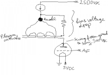
Say tube cathode is grounded, and plate hangs off plasma cathodes. The discharge is dropping the voltage from B+ at the anode to the top of the plate, which only needs enough voltage to be able to be able to swing the maximum audio amplitude. The plasma cathodes (tube plate) never exceed a few hundred volts above ground.
Here's what I mean (see attachment).
The resistor there doesn't change anything regarding my question, I could just as well have left it out and used a plain cathode instead of MHCD.
If this is in resistive mode, then the plate only swings a few hundred volts, the AF signal, as most of the bias voltage is dropped by the discharge.
If this is in constant voltage mode, then the discharge still drops most of the voltage, and the tube regulates current with almost nil voltage swing, though I'm not sure what the voltage at the plate would be in that case.
I don't even know if a current source is necessary, as the anode could hang directly from B+.
Attachments
Er, the CCS idea was under the impression that the arc was CV like a zener. Then the *tube* would best be variable CCS (aka transconductance amplifier).
In this situation, are you sure it is wisest to place all that bias and so little AC voltage across the discharge? Best performance for a class A amplifier will always be at 1/2 B+ or so (ballpark), depending on requirements and characteristics. Point being, you get some voltage swing at the proposed level, but if you back off bias a bit (enough that cutoff or other distortions are met only at the peak of output signal), you get MORE ACV, and thus audio swing. Point being: your proposition implies the discharge stabilizes (i.e. reaches the 2nd area of the graph shown elsewhere) at around 1500V.
Tim
The point is that the bigger the bias is vs. the AC variation, the more linear the plasma is in sound generation.
I don't see what the "best class A is half B+" has to do with here, as from the point of view of the tube, the B+ is whatever the plasma transfers to the lower electrodes.
If the plasma is in the resistive mode (not constant voltage), I guess one can think of it as if the discharge is a resistor loading the tube's plate, such that the plate voltage only reaches up to a fraction of the top of that resistor. The discharge drops at least 2 kV, and at most B+ (2.5 kV), and this 500 V is the range within which the tube's plate voltage plays.
If the plasma is in the constant voltage mode, then the discharge is like a constant voltage source to the plate (say 2 kV), such that the plate always sees, say 0.5 kV.
Transconductance configuration I think works in both cases. Does that make sense?
Sorry, I'm always thinking in terms of maximum power. But power is power - distortion can be corrected, clipping can't.
AFAIK, no one here knows if the discharge will have a sqrt(x) (i.e., x^1/2), x, x^3/2, x^2, or e^x characteristic. Presumably it WILL have a predominant second-order distortion, being class A. If it's sqrt(x), that will correct half the tube distortion, and better yet, x^2/3 would correct it fully. If it is linear, your amplifier must be linear for a linear sound output. If x^2, it will add to the distortion of the tube and require small levels or corrective measures. For instance, you could use a high distortion preamp/driver tube to predistort and cancel it (yeah, you get IMD, but distortion isn't my primary worry here, I'd just like to see it work!).
Yes, transconductance works anyway (because current is changing), but here you have a (presumably) resistive load, so it's easier for a tube to drive, since... tubes have that nasty x^3/2 transconductance curve. I think Gm amps have a CCS output (variable CCS to be exact), as voltage amps are taken as a CV output. They each have their use, most loads (speakers, power inputs, etc.) like CV though.
I'm still inclined to think this discharge will prefer a CCS source. My imagination can't disconnect "negative resistance" and "gas discharge".
Tim
Cooling is passive (environment) as the amplifier can only pump energy in, not suck it out, and thus the exponential rather than linear relationship. That's why the AF modulation should be small compared to the total bias to reduce this distiortion. I'm not sure what kind of feedback can be used to cancel it. If the exact function can be measured, then some electronic mechanism to generate it can be found. Another possibility is to use a photocell (is a photocell linear?) or other method to actually measure instantaneous temperature and use that as feedback (that's sot of analogous to the motion feedback technique that has been applied to some speakers).
Regarding the transconductance problem you mention, do all tubes have it, or does it vary depending on whether it's a triode, etc.?
Like I said, with the lower voltage as I explained, a transistor circuit may be possible. Perhaps that would be better?
Regarding the transconductance problem you mention, do all tubes have it, or does it vary depending on whether it's a triode, etc.?
Like I said, with the lower voltage as I explained, a transistor circuit may be possible. Perhaps that would be better?
Temperature decay, like charge decay and a host of other things that reduce based on the difference, are exponential with respect to time. A capacitor discharges, a block of metal cools down, the amplitude of a swinging pendulum drops to zero. However, a given power input across a medium (be it metal, ceramic, fiberglass or air) is polynomial. Uniform, solid materials like metal are linear (x^1), insulating materials tend to be a bit worse at higher temperatures (x^3/2 or so); air, depending on convection allowed, may be anything from x^3/2 to x^2 or even x^3 I suppose. Radiation (mostly at work for temperature differences above 1000øF) goes x^4!
Just to clarify.
We're dealing with electrical fields here too, so I'd suspect something along the lines of x^3/2 (or the inverse) or x^2. Please try to assemble and measure an array, then we'll have some information to go on!
Which reminds me, ALL tubes have the 3/2 power law inherent in them, just as ALL semiconductors have exponential behavior inherent in them.
Oh, and yes - including the discharge in the feedback will be a very good idea if it emits light suitable for a phototransistor. 🙂
Tim
Did you take a look at the patent? Check out Hill's calculations. (BTW he seems to ignore heat lost by radiation...) Can we not derive the exact nonlinearity from the equations? It would be better if we have both a theoretical and experimental result when trying to compensate, rather than just the latter.We're dealing with electrical fields here too, so I'd suspect something along the lines of x^3/2 (or the inverse) or x^2.
OK, but I'm still waiting for some parts. Moreover, as I don't have any large tubes, I can only do DC experiments. But there is another more serious problem here: the MHCD cathodes. For my initial test, I used thin copper and mica, and holes about 1mm, as that's as small as I could make them. Three issues result: first, copper lasts very little time under these conditions and I need something like tungsten or an alloy whose name currently escapes me; second, mica flakes apart and I need something like alumina ceramic and I can't source any as thin as needed (0.5 mm); and third, I'm unable to drill clean holes of the needed sizes (starting as small as 0.2 mm).Please try to assemble and measure an array, then we'll have some information to go on!
Nah, I'm thinking this wont work. The light frequency changes with temperature, and light emission is not just thermal but mostly from the ionization. The only way to do this is to have a small, linear, very fast (low heat capacity) temperature probe in the discharge.Oh, and yes - including the discharge in the feedback will be a very good idea if it emits light suitable for a phototransistor.
I still think it would help to have the nonlinearity derived from theory so I know what I'm looking for in the measurements.
No; unless this microhollow thing is vastly different from any discharge I'm familiar with, the ionized gas will emit spectral lines inherent to the gasses. In visual terms, it ought to range from purple (oxygen I think) to blue-white (hotter nitrogen arcs). But that's just how we see it, to say nothing of how semiconductors may respond to different wavelengths differently.
I don't know nearly enough plasma physics to be able to come up with a theory of how this thing expands vs. input such that it creates an acoustic wave.
Can you try thicker copper plates, different sized holes etc.? The local hardware store should carry drills down to #60 to #80 (or whatever they use in your measurementally *******ized country 😉 ), which should be plenty small. I also wonder if larger holes may be useful.
Tungsten can be had in rod form as TIG rods from the welding supply store - might be able to forge one flat and drill a small hole in it. I recall forming must be done hot (>500øF depending on purity) else it's hard as the gates of hell. If aluminosilicate is acceptable, a bit of fire- or ball clay from the pottery store might be useful. It'll be more resilient than (though not as flexible as) mica but have about the same melting point. Hmmm, I can't think of any substitutes for straight alumina though. Would quartz glass be suitable? Pure silica has a melting point of 3200øF or so.
Oh, and what patent is this? I missed the reference...
Tim
That's why I asked you to take a look at the patent. Perhaps you can help me figure that part out. It's US patent 4219705. Use http://free.patentfetcher.com/ to pull it in PDF format (rather than having to flip through the TIFF scans that the USPTO site presents).I don't know nearly enough plasma physics to be able to come up with a theory of how this thing expands vs. input such that it creates an acoustic wave.
The method of operation of the microhollow cathodes is very different from a regular discharge (such as the large discharge here, except that it's missing a normal cathode fall region as the MHCD replaces it), and in that regard I'm just following what has been done. You are right, however, regarding the spectral lines -- most energy of the large discharge is probably spectral emission, but wouldn't some be still blackbody radiation?Can you try thicker copper plates, different sized holes etc.?
I have no idea how to do that...Tungsten can be had in rod form as TIG rods from the welding supply store - might be able to forge one flat and drill a small hole in it.
I think not. According to Jay Philippbar who owns a pair of Plasmatronics, his plasma is 3400 deg. C or 6200 deg. F.Would quartz glass be suitable? Pure silica has a melting point of 3200øF or so.
Note: I have finally gotten replies from JP regarding my questions. The power supply is inefficient and it draws 1200 W from the mains, but the plasma is only two channels times five cathodes times 1250 V drop times 25-30 mA, so about 160 W (average). Although I cannot share the schematic he sent me, I can say that our guess was correct -- it is a voltage controlled current sink (6MJ6 pentodes driving each cathode), and in the Plasmatronics the discharge is normal (constant voltage). Acoustic production is inefficient, as expected; with 1 kHz crossover, 115 dB at 1 m. I'm hoping for beat this, and crossover around 500 Hz, as though my power supply draws about as much from the mains, I don't have as much losses, and using a larger plasma will lower the response.
Are you familiar with any math software? Hill's plasma formulas can be solved in full without his simplifications using a current maths package (at least numerically). If I knew how to use Mathcad or Maple I'd have done it already. This would tell us the exact nature of the nonlinearity that needs correction (or if it's significant enough to need correction at all).
Ok, I'll check out the patent. Could you e-mail me the schematic?
Forging... take a chunk of metal, heat it (if necessary), pound between two chunks of heavier metal (typically some sort of anvil and a hammer). I don't know if you'd be able to forge tungsten very far without shattering it though.
I don't have MathCad or whatever, but I can prog some formulas in QBasic and graph them. If nothing else, I can putz around with them...I'm a math head.
Tim
Naaaaugghhh!!!QBasic

An externally hosted image should be here but it was not working when we last tested it.
An externally hosted image should be here but it was not working when we last tested it.
- Status
- Not open for further replies.
- Home
- Amplifiers
- Tubes / Valves
- HV tubes