In these decadent silicon days, most resistors are only good for 250V. Philips/BC Components MRS25 are good for 500V RMS according to the 1989 data sheet. In general, higher power components have a higher voltage rating. Often, 2W resistors are 700V. I am told (but don't have any data sheets to confirm it) that there are some Japanese 2W metal film that are good for 2kV.
I'm not sure what you are implying here. How exactly were you lax? I don't follow.
I was lax because:
1. I assumed (without actually knowing) that you had some experience with high voltages.
2. I neglected to post warnings, which ought to be done because this is not a private conversation.
EC, I've been using standard carbon comp resistors (the big brown jobs with three value stripes and a tolerance stripe) for voltage equalization. It's possible that these are NOS components- I get them from a local ham radio supply shop rather than Digikey or the like. Do you have an idea about what the voltage ratings of these are?
Hi,
Not EC but :
These could be NOS Stackpole or AB carbon comp which are normally rated for 500V in both 1W and 2W powerratings.
I checked with IRC, TRW, Speed, RCA, Ohmite, Ohmic, Kamaya and others and they also are rated the same way as from 5R4 up.
Cheers,😉
Not EC but :
Do you have an idea about what the voltage ratings of these are?
These could be NOS Stackpole or AB carbon comp which are normally rated for 500V in both 1W and 2W powerratings.
I checked with IRC, TRW, Speed, RCA, Ohmite, Ohmic, Kamaya and others and they also are rated the same way as from 5R4 up.
Cheers,😉
Just remember you're asking the wrong device. Actually, any device is crap. Tubes have a 3/2 power law and semiconductors are exponential. So in either case, you'll have to use NFB (current feedback; a large cathode bias resistor, or better yet, a CCS, will serve well) to linearize the discharge, assuming you will go with just the constant voltage region.
So you don't know anything else about that diagram? There are a lot of variables: medium (helium/argon/CO2...), pressure, temperature (may not effect it much), electrode spacing, dimensions, I could go on.
Tim
So you don't know anything else about that diagram? There are a lot of variables: medium (helium/argon/CO2...), pressure, temperature (may not effect it much), electrode spacing, dimensions, I could go on.
Tim
OK. For reference again the graph is here.
In the constant voltage area, the amplifier essentially acts as a AF modulated current regulator. I was under the impression that voltage-in-current-out amplifiers are called transconductance amplifiers. I haven't found any information on audio use, (after all this is not a usual type of load). In SPICE simulations, several common audio amp circuits I tried completely fail to drive this. To simulate this load in SPICE I used an idea from some website dealing with simulating a spark gap:
I only used part of this circuit, the glow simlulating zeners, as the rest is not applicable here.
F-G occurs because increasing voltage in that region makes the discharge use more area of the electrode. If I make the electrode sufficiently small, then it becomes an abnormal discharge (G-H region), which I'm not sure how to represent as a load in SPICE.
I'm still experimenting with electrodes, so that's why I was hoping I could have an amp for experimenting that will work in both conditions.
Now take a look at the attached image (source can be seen in upper left). On the left you see their setup. The use of the microhollow cathode discharge itself as a cathode allows a large volume atmospheric pressure plasma to form which is much more stable and less likely to transition to an arc than if a simple cathode were used. The graph's third section shows that the load becomes essentially resistive in that region.
It is not clear to me, however, if Hill's result (as described in his patent) that short-duration input power variations result in proportional pressure variations, making this useful for sound reproduction remains true here, in the sense of how linear the relationship is. Using power supplies for the MHCD and the MHCD sustained discharge may be better.
In the constant voltage area, the amplifier essentially acts as a AF modulated current regulator. I was under the impression that voltage-in-current-out amplifiers are called transconductance amplifiers. I haven't found any information on audio use, (after all this is not a usual type of load). In SPICE simulations, several common audio amp circuits I tried completely fail to drive this. To simulate this load in SPICE I used an idea from some website dealing with simulating a spark gap:
An externally hosted image should be here but it was not working when we last tested it.
I only used part of this circuit, the glow simlulating zeners, as the rest is not applicable here.
F-G occurs because increasing voltage in that region makes the discharge use more area of the electrode. If I make the electrode sufficiently small, then it becomes an abnormal discharge (G-H region), which I'm not sure how to represent as a load in SPICE.
I'm still experimenting with electrodes, so that's why I was hoping I could have an amp for experimenting that will work in both conditions.
Now take a look at the attached image (source can be seen in upper left). On the left you see their setup. The use of the microhollow cathode discharge itself as a cathode allows a large volume atmospheric pressure plasma to form which is much more stable and less likely to transition to an arc than if a simple cathode were used. The graph's third section shows that the load becomes essentially resistive in that region.
It is not clear to me, however, if Hill's result (as described in his patent) that short-duration input power variations result in proportional pressure variations, making this useful for sound reproduction remains true here, in the sense of how linear the relationship is. Using power supplies for the MHCD and the MHCD sustained discharge may be better.
Attachments

My favourite tube for huge amplifiers is the 100TH triode. Its a bonza of a tube designed for RF amplifiers in the 1940's, works well at audio, and looks great when lit up - very impressive with a top cap for the anode and a side connection for the grid.
Phil
Phil

If I want the audio frequency output to vary over a limited range of the total bias, say a few hundred volts amplitude centered around a 2 kV average, can a tube with lower dissipation be used (to save money)? For example, say the base plasma power is 400 W, with an additional 100 W going into the audio frequency modulation. What's the minimum wattage rating of the tube needed?
You're in class A (constant average current, constant voltage if it doesn't turn to arc) so dissipation is constant. Loadline is perfectly vertical (which begs the question of how power output is obtained.. I'm going to guess a difference in power due to changing size and thus radiating sound, of intensity which pales in comparison to average power consumption of the discharge, hence you wouldn't notice it on the loadline). Yes, you're operating on transconductance.
So to sum up, tube dissipation depends on idle current times idle voltage, plus a little extra for arc protection or something.
Tim
So to sum up, tube dissipation depends on idle current times idle voltage, plus a little extra for arc protection or something.
Tim
Take a look:
Power variation creates pressure differences, as long as the variations are small enough not to give time for the plasma to equalize pressure with surrounding air (and increase volume instead, by ideal gas law). The use of microhollow discharges as cathodes removes cathode fall region instabilities and decreases the problem of glow to arc transition.
I don't think it matters where the ground is in this circuit, it should still operate the same. Now if I put the ground between the bias and modulator instead, wouldn't that make the tube only have to dissipate the modulation portion of the total power? Or am I missing something?
Also, I'm not sure that I need a transconductance amplifier, because I don't really know the I-V characteristics of this thing at audio frequencies (at DC it's pretty much a resistor). Rather than a voltage controlled voltage or current source, it would be better to use a voltage controlled power source, as that would work in any case.
The other thing I'm unsure of is if it would be better to have a separate supply for the MHCD array, rather than the resistor I put there (biasing with a resistor is something I saw in a paper dealing with DC characteristics). And of course, it's possible to modulate the plasma cathodes instead of the anode, which would make this more similar to Hill's design where he drives the cathodes, but I don't think it matters, and would make this more complicated.
An externally hosted image should be here but it was not working when we last tested it.
Power variation creates pressure differences, as long as the variations are small enough not to give time for the plasma to equalize pressure with surrounding air (and increase volume instead, by ideal gas law). The use of microhollow discharges as cathodes removes cathode fall region instabilities and decreases the problem of glow to arc transition.
I don't think it matters where the ground is in this circuit, it should still operate the same. Now if I put the ground between the bias and modulator instead, wouldn't that make the tube only have to dissipate the modulation portion of the total power? Or am I missing something?
Also, I'm not sure that I need a transconductance amplifier, because I don't really know the I-V characteristics of this thing at audio frequencies (at DC it's pretty much a resistor). Rather than a voltage controlled voltage or current source, it would be better to use a voltage controlled power source, as that would work in any case.
The other thing I'm unsure of is if it would be better to have a separate supply for the MHCD array, rather than the resistor I put there (biasing with a resistor is something I saw in a paper dealing with DC characteristics). And of course, it's possible to modulate the plasma cathodes instead of the anode, which would make this more similar to Hill's design where he drives the cathodes, but I don't think it matters, and would make this more complicated.
I was imagining the plate hanging off the cathodes. Tube handles DC bias.
You could hook it up to a normal audio amplifier through a transformer, similar but almost inverse to an ESL as, according to the data you've presented, it has a nearly flat (i.e. zero) dynamic resistance. As a result, it will require a lot of current to develop a change in voltage across the discharge, which is what the transformer and constant-voltage-output amplifier before it are trying to accomplish. Constant voltage is always an unstable situation with discharges anyway, things like to explode. That's why I've been imagining a constant current output amplifier, which you haven't I guess? 😕
Tim
I've been imagining constant power output amlifier, as I said above.
So if I was to use the tube to both do bias and audio, it should be rated for the total power? So I'd need something like a 3-500C after all.
So if I was to use the tube to both do bias and audio, it should be rated for the total power? So I'd need something like a 3-500C after all.
Ehh... constant power output? How's that work with dynamic music and a volume control.. 😕
Like I said, if you use a transformer, you can use anything, and skip the class A dissipation. But it might not work as well.
Tim
Like I said, if you use a transformer, you can use anything, and skip the class A dissipation. But it might not work as well.
Tim
I meant to say voltage controlled power output. Output power is proportional to the voltage driving the amplifier.
I'm not familiar with how you would accomplish that, nor why. Seems to me you'd get a nice square root transfer curve and the respective THD and IMD created by such...
Tim
Tim
Over a small enough time interval, the compression sound wave created by the plasma is proportional to the input power change. If the plasma was resistive, I could just use voltage or current ouput as power would be proportional, but I don't know that I can make that assumption.
A very generic schematic of a voltage-to-power amplifier is shown on page 4 here, http://www.tubecad.com/email_2001/e0829/e0829.pdf, but I'm going to need some help figuring out how to design an actual circuit...
A very generic schematic of a voltage-to-power amplifier is shown on page 4 here, http://www.tubecad.com/email_2001/e0829/e0829.pdf, but I'm going to need some help figuring out how to design an actual circuit...
I'm under the impression that you are operating in a constant-voltage region, where current is proportional to power (P = V*I, V constant > dP = V*dI, to use calculus). As a result, the impedance will also be low, requiring a high impedance drive to prevent overloading something, distortion, or other unwanted bad things.
Tim
Tim
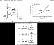
There are three glow discharge modes using two normal electrodes: subnormal (transition from dark discharge, V inversely proportional to I), normal (V constant as increasing I just makes more electrode surface to be covered by discharge), and abnormal (V proportional to I until glow-to-arc transition).
But I'm not using normal electrodes, but a plasma cathode, where a microhollow discharge is the electron source instead of a simple cathode. Take a look at the attachment. In the equivalent circuits, R2 and R4 are the MHCD and the main discharge, respectively. This implies not constant voltage to my understanding. Moreover, these are all DC conditions. I have no idea how it would behave at audio frequencies, and with multiple MHCDs and gas flow (needed to shape the plasma properly).
That's why I was thinking of an amplifier that will work in any case.
Oh yeah, that diagram. Seems to me a simple amplifier would suffice, with some NFB to correct the transitions (unless you're running in just one region) and variable impedance (if applicable).
Tim
Tim
- Status
- Not open for further replies.
- Home
- Amplifiers
- Tubes / Valves
- HV tubes