2Kv peak= 4Kv peak-peak.
An amp that has a 2kv supply will produce a 2kv peak-peak signal (0V to 2 kv) or 1Kv peak.
The same amp, but only two of them, when operated in differential or BTL (Bridge Tied Load) will produce 4Kv Peak-peak or 2Kv peak.
jer 🙂
An amp that has a 2kv supply will produce a 2kv peak-peak signal (0V to 2 kv) or 1Kv peak.
The same amp, but only two of them, when operated in differential or BTL (Bridge Tied Load) will produce 4Kv Peak-peak or 2Kv peak.
jer 🙂
Max power dissipation is 20W real life would be 10W which, in turn, equals to 10 mA of current, which, in turn is too low as I have already stated. 1000pF panel @ 10mA means pitiful 10V/uS... 200pF 50V/uS is no good either
I see a lot of confusion about how much voltage and current you actually need. That all depends on your panel design and the frequency range you want to cover. The impedance of an esl drops with frequency so current requirements increase with frequency. At 100hz you need next to nothing. On the other hand, the energy content of music drops at higher frequencies. At 20khz you don't need much voltage swing anymore and consequently not much current either. Somewhere in the middle of the freq range the current will max out.
I analyzed the energy content of lots of different kind of music and found out that up to 1-4 khz you can expect transients of full amplitude. So you really need to base your design on the assumption that you can expect full voltage swing up to 4 khz if you don't want to compromise.
I once did measurements on actual stator currents. Built a fast peak detector, battery powered, connected to a current measuring resistor in series with the stator of a large full range segmented wire esl. Don't remember the exact capacitance but it was somewhere in the 500pf range for the whole panel. A small strip of approx 100pf was connected directly, the rest over a couple of resistors (200k or so, segmentation). Using this setup I measured currents flowing into the esl while playing a wide variety of music. Long story short: you need at least 25mA per kV for a panel this size, twice that if you don't want to compromise. And yes, peak currents always occur in that 1-4 khz range.
This is for a fullrange panel. Panels that do not need to produce deep bass can have lower spacing, thus higher sensitivity at the price of more capacitance. Basically you're trading voltage for current here.
The current requirements for a electrically segmented panel is much less than that of a full single panel such as the ML's and other common DIY built designs.
I while back I had calculated that it takes about 900 watts to fully drive a 1' X 4' panel with an average D/S of around 1.5mm to 2mm or so to its fullest capability at 20Khz.
But the need for that much power is quite different by the time you add the slope equalization at -10db per decade of the rising frequency.
That is a very good observation maudio!! 😉
jer 🙂
That depends on what you want to extract. But I do agree they are not good models.
On the other hand I can understand manufacturers also do not want to give too much details away to competitors.
You can, e.g., only get models from Toshiba by written request, from a company (commercial customer).
My 2 pfennig -- aren't we working in the sub-threshold region of the mosfet anyway? (Not the square law region) so you have to run Id vs Vgs graph over a much lower range of currents and build your own EKV model. These low Id/Vgs data aren't published by the manufacturer so you'll need a curve tracer.
I don't have a FQP3N80C on hand, but will get a couple from DK on the next order, and put them through their paces on the 576.
Attachments
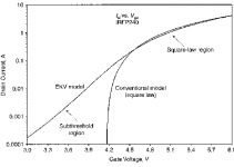
Just so ya know, the EKV model is Level 44, at least in Multisim. Cordell uses a VDMOS model and EKV model in parallel for the sub-threshold region -- and MSIM does not support LTSpice VDMOS.
Want to bump this up.
I'm looking at building a ESL sub with 4m2 panel. Planning to play down to 16Hz and up to 150Hz need an amplifier that can handle the impedance.
Would need some hints...
I'm looking at building a ESL sub with 4m2 panel. Planning to play down to 16Hz and up to 150Hz need an amplifier that can handle the impedance.
Would need some hints...
Last edited:
Hi ESL63
Have exactly the same idea for bass... should be super dynamic as well, because at those frequencies different regions of the panel won't be out of phase with each other...
I think for direct drive here, you might get away with something using beam triodes like 6HV5 - you won't need a huge amount of current at low frequencies.
But I would still be tempted to use a transformer due to the crazy voltages involved...
Anyway, would love to hear what you have in mind for the panel construction if you decide to document this at some point.
Best,
cv
I have several pairs of esl 63's, eight or nine... and they are the best speakers yet to be found, specially if you use a decent active filter (150Hz approx..) and dipole subwoofer.
I also have a pair Beveridge 2SW2 (modyfied) with dipole bass speakers.
Esl 63's has the most natural soundstage, and the Beveridges is not bad either, specially when more than one person at the time are listening. The bass reproduction is very important for both speaker types as well as good amplification.
Me and a friend is working on an almost direct driven amlifier for the ESL 63s with 300B as drive stage and double GM70 as push pull output stage driving double 1:3,5 ratio transformers. Building some huge bass panels has been a dream ever since i tried 3 pairs of ESL63 per side placed in a U shape with a big fiber board on top. Where the 2 side speakers was cut off above 100Hz. And the forward pointing one went full range.
Anyway driving 100nF-200nF 4000volts peak to peak at 200Hz is interesting challange.
If i find out a good way i will share it.
Hi
That's a very large capacitance (is that reflected after the stepup)? My ML CLS panels (around 0.7m^2) measure around 1-2nF each. So a bass ESL of 4m^2 shouldn't need to me more than about 10nF (it would have a bigger stator spacing than the CLS too)? Am I missing something?
Once drove them briefly with a 4212E SET into a 1🙁0.75+0.75)... sounded tremendously promising but more power required!
But for a few kV into 10nF shouldn't require more than 50mA, which is probably within the means of say a bridged SRPP of 6HV5A or similar tubes.
Still, I can imagine the U shaped setup producing some super precise lower mids... will be following your progress with interest!
Hi There!!
200nf has an Xc=4K ohms at 200Hz.
At 150hz it is 5.305K.
With a 2Kv peak voltage you would need .500ma of current.
But at this setting the Xc would equal the amps output impedance and you would only get half of the supply voltage swing on one stator at 1Kv peak for the swing.
Typically in my simulations I have found that I had to design for a target frequency (3x ? maybe) of at least 4 to 5 times higher than my highest operating frequency in order to have the output drop no less than in the range of 1db to 2db for a roll off compared to the rest of the bandwidth that is ruler flat.
My target was of course 20Khz but it has the same effect at the lower end of the scale.
Common for any SE Class A amplifier design.
Also if you are using a DC blocking cap on the output this also forms a voltage divider and the output cap will have to be 10x the panels capacitance in order to keep the output voltage swing 90% of the total that is available and 100x the stator capacitance for only a loss of 1% of the total swing.
200nf or .2uf would be quite a very large array at that!!!!
Especially if you are providing enough D/S to even be able to produce frequency's below 200Hz with any kind of volume and quality.
I have thought of such a system myself with something like 32 or 64 square feet of area and at least .1" to .125" of D/S and even with the possibility of using a compounded Isobaric diaphragms for better control of their movement.
According to my calculations such a system just may be able to produce close to 115-120db at 20hz!!
I forget what my projected capacitance would be at this time without re-calculating it all.
I believe there was another thread on this very subject (ESL Bass) a while back and I had described the very same thing then.
I am so itching to get my DD amp running this summer now that I have the FET's to work with and a few more new panels made.
Cheers and Good Luck!!!
jer 🙂
- Status
- Not open for further replies.
- Home
- Loudspeakers
- Planars & Exotics
- HV Transconductance Amp - Idea