If a simplicistic mosfet design is desired here is one WITH transformer:
Zero Feedback Transformer Audio Power Amplifier
Zero Feedback Transformer Audio Power Amplifier
Calvin,
1) Why not build fully balanced ?
2) If you use a CCS instead, you won't need PNPs (I know you lose 6dB current gain).
http://ixdev.ixys.com/DataSheet/DS98729A(IXCP-CY10M90S).pdf
2SA1968 & the like are unobtainium. At best you can cascade 2x 2SA1156.
3) The Pass STAT is also transconductance. In theory one can also use a Riv and buffer.
Have not tried, so not sure what distortion is like.
Best wishes for the New Year,
Patrick
And you probably like this :
http://www.onsemi.com/pub_link/Collateral/ENA2236-D.PDF
Cannot find a easy source though ...... 🙁
Patrick
http://www.onsemi.com/pub_link/Collateral/ENA2236-D.PDF
Cannot find a easy source though ...... 🙁
Patrick
That's a very interesting find Patrick. Low capacitances and such.
Group buy? 😉
Edit: I also see that Sanyo has been acquired by ONsemi. A logical step for ON come to think of it.
Jan
Group buy? 😉
Edit: I also see that Sanyo has been acquired by ONsemi. A logical step for ON come to think of it.
Jan
Last edited:
If a simplicistic mosfet design is desired here is one WITH transformer:
Zero Feedback Transformer Audio Power Amplifier
Do I understand it right (I am no engineer) that the transistors in the ZEUS needn't hold much more than the voltage swing? And would a direct drive with 1000 V types possible then?
If one fet pulls it's drain towards ground, the other one will be pulled upwards. So the fets need to withstand twice the power supply voltage (plus some more for safety margin, we're talking inductive loads here).
But can't really see the point in building a direct drive amp with an output trannie 😕
But can't really see the point in building a direct drive amp with an output trannie 😕
Hi,
@maudio: the fact that SRPP achieves symmetrical pushpull current swings into a certain defined ohmic load kept me from further evaluating that topology. Still though it kept my interest, as some of its features would come quite handy, like high gain (especially with MOSFETs), low parts number count, possible good efficiency (for class-A).
The pushpull feature of a SRPP would be most desirable towards high frequencies. Do You think, that a SRPP with an idle current set to match for the ESL impedance at say 10kHz would be feasable? The lower current demand towards lower freqs could easily be served by the SE nature of the SRPP in that freq-range.
I also remember a article of J.Broskie in his TubeCadJournal, about modding a SRPP to match capacitive loads. IIRC he suggested to exchange or to expand the modulating anode resistor -spanning between the active devices- by a CCS. Need to find that one again.
IXYS is always a good for a surprise.
HV-MOSFETs:
IXTK/IXTX 5N250, 2500V, 5A
IXTA/IXTH/IXTV 02N250, 2500V, 200mA
IXTL 2N450, 4500V, 2A
HV-Depletion-MOSFET:
IXTH/IXTT2N170D2 1700V, 2A
For most of these IXYS supplies models (see attached files).
Hacked the attached test circuit into LTSpice IV, but couldn´t get them running properly.
I used the .lib files from the zip.files and just put them into a more convenient, readable style.
Anybody got a solution to get them working properly??
jauu
Calvin
Attachments
-
MOSFET- Id over Vd - Test.asc.txt742 bytes · Views: 78
-
irfru9310.lib.txt2 KB · Views: 74
-
FQP3N80C.lib.txt1.6 KB · Views: 73
-
IXTH02N250.lib.txt1.4 KB · Views: 78
-
IXTK5N250.lib.txt1.4 KB · Views: 75
-
IXTL2N450.lib.txt1.4 KB · Views: 74
-
IXTH02N250.zip2.6 KB · Views: 77
-
IXTH10P60.zip2.9 KB · Views: 71
-
IXTL2N450.zip4.5 KB · Views: 82
-
IXTK5N250.zip2.9 KB · Views: 70
Last edited:
But can't really see the point in building a direct drive amp with an output trannie 😕
Would an ESL mind the DC offset, if it's the same on both stators?
Last edited:
Sorry, I just should have read the description again (it was years ago that I stumbled across this design). The transformer is necessary for the operation and doesn't just compensate for the DC offset.
> Group buy?
From whom ?
I cannot even buy direct from Onsemi .......
Do you know their distributor in NL ?
> Anybody got a solution to get them working properly??
No. I can get one or two the IXYS to work.
But they vary by so much in their complexity that I would not trust the results 100%.
Especially that most of them are used for switching purposes.
I also cannot get some of the OnSemi to work.
I have sent them a email asking them to check.
Perhaps you could do the same to IXYS .....
Building is more reliable in the end. 😉
Patrick
Hi,
@Alex
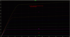
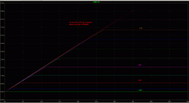
The DC sweep is a method to plot the Id over Vds curves with stepped Vgs.
It´s simply to evaluate if the model is working basically right and how the plots compare to Datasheet values.
Attached are the sims of IRFP240(Cordell Model), FQP3N80C, IXTK5N250, IXTH02N250, IXTL2N450.
The IRFP240 model is obviously the most sensible.
The Fairchild model is already flawed. It shows sharp bends in the curvature.
The IXYS models as are, are useless. Theyare not even consistent amongst each other. Each presents a different failure. 😕😡
As the veryhigh voltage devices aren´t exactly cheap, models which are at least halfways reliable would be very helpful.
jauu
Calvin
Attachments
> The Fairchild model is already flawed. It shows sharp bends in the curvature.
> The IXYS models as are, are useless.
That depends on what you want to extract. But I do agree they are not good models.
On the other hand I can understand manufacturers also do not want to give too much details away to competitors.
You can, e.g., only get models from Toshiba by written request, from a company (commercial customer).
If you plot Id vs Vgs, which is what we are primarily interested in, then both Fairchild & IXYS models work to an extent.
There are other embedded faults, like gate current too high, etc.
For industrial (switching) users, those faults may not be important.
And let's face it, who (as manufacturer) cares about audio analogue ?
How much business volume are they going to get from audio, not to speak of DIY ?
Would we ever order 100k pieces of stuff ?
Patrick
Well all I need to read some on mosfet design to recall what I used to learn back then. And make sensible model by measuring the real thing first.As the veryhigh voltage devices aren´t exactly cheap, models which are at least halfways reliable would be very helpful.
jauu
Calvin
Never the less here what you need:
http://www.cree.com/~/media/Files/Cree/Power/Data Sheets/C2M1000170D.pdf $5.5 apiece at DIGI... no capacitances quite rugged.
Not like first generation that lasted around 2khrs.
Regards...
Perhaps a stupid question.
But I am missing some specification numbers, such as required output voltage levels, and load capacitances ??
What does the amplifier actually need to deliver ?
Patrick
But I am missing some specification numbers, such as required output voltage levels, and load capacitances ??
What does the amplifier actually need to deliver ?
Patrick
That was exactly where I was at when my last panel fried !!!
But 20Vpeak into 1:160 at 3200V peak was plenty loud at +105db or so at 1 meter !!
I was runinng at least a 6.8KV bias at the time.
My measuremnts nearly matched the ESL simulator page for my panels dimensions.
5V peak was plenty for normal listening hitting an ocassional 10V peak in to the step-up.
So, anything below 2Kv peak was good for the most part.
My 3.25" x 9.75" panels capacitance is about 35-50pf.
A push pull amp (BTL) with a 2Kv power supply will produce 4Kv peak. 😉
jer 🙂
Last edited:
Hi All
In an earlier post someone mentioned trying a transconductance amp on an ESL and was puzzled by the poor sound quality – too much bass and falling uppers.
It occurs to me that the Walker equation, which suggests constant-current drive for an ESL, applies only to ESLs that behave as a point source (e.g., Quad ESL-63 and successors).
In practice most ESLs operate, for at least part of their frequency range, as a line source, for which Baxandalls version of the Walker equation applies. And that requires the current to increase in proportion to the square root of frequency to give flat equalisation. This means transconductance amp is inappropriate for most ESLs.
The differences are as follows
Walker : P = Isig . Vpol / (2. pi. c.r.d)
Baxandall: P =Isig.Vpol/(2.pi.d.h.sqrt(c.r.f))
P = pressure
Isig = stator current
Vpol = polarisation voltage
c = speed of sound ~330 m/s
r = distance to listener
d = stator-diaphragm distance
h = height of stator
f = frequency
hope this helps, regards
Rod
In my earlier sim's I had found the output impedance of the amp had to be much lower that that of the panel at the highest frequency.
If you design the amp with a set current that equals that of the requirements to drive the panel then you will get half of the voltage swing rather than all of the way to the rails.
This is because the output impedance and the panels impedance are equal and form a voltage divider to the power supply rails.
This is true for any class A SE amplifying stage.
This brings me to my original statement of designing for at least 5 times the target frequency and using a higher current bias through the output devices as such that this will reduce the effect of voltage droop at the highest target frequency (20Khz).
It had been a long long time since I had played with those sim's, so I don't have any solid numbers to give at this time.
Due to the rising response of the panel you may be able to get by with only about 3 times the required current rather that 5 or 10 times and accept the voltage drop as a form of equalization.
I had settled on a number that only gave a 1db to 1.5db drop at 20Khz as this was much less of a factor that a full 3db drop in voltage.
It seems to me that it does make a difference as to how you are using the ESL.
As in a nearfield situation, such as my little desktop model, you would want a fairly flat response from the amplifier.
And in an open room linesource dipole fashion, the reduced current design (current drive) may be a better choice.
Before I had decided to start building one, I needed find the voltage requirements needed to drive a panel nicely as previously mentioned.
And it also was the reason for burning them up a few times. 😉
FWIW
jer 🙂
- Status
- Not open for further replies.
- Home
- Loudspeakers
- Planars & Exotics
- HV Transconductance Amp - Idea

