Exactly like that! The sloping edge moves from the falltime edge to the risetime edge.
I don't think this has any effect on results in our test vessel. Just intereting.
I'm in the wait for parts to arrive mode.
Know, just to clarify which build you would suggest.
I have a B&K 3011B Function Generator on the way.
The B&K 3011B has two output connections, Output and TTL/CMOS. All are 50Ω sources.
As I understand the spec sheet, Output that will supply a variable 20Vpp AC square wave into an open circuit.
The Output connection also has a ±10V DC offset available.
The TTL/CMOS will output a variable 14V DC pulse into an open circuit.
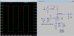
So, that being my driver, I have a choice of DC pulse drive circuit or the push-pull circuit.
In another post you said, "The tweak with PP is fine, but can very well be achieved by shifting the bias to just -5v, so a 5v pulse will swing between -5v and 5v a total of 10v (doubling the pulse height). This is as simple as it can get and probably more reliable, you know where I would put the money on."
And showed this schematic,
https://www.dropbox.com/s/5ro88b2n5wlutnh/Pulser ±5vpp input grid drive.jpg?dl=0
Is this the circuit you would go with at this time?
I will have a voltage divider on the output to monitor it with a scope, Since I can adjust the grid drive amplitude and add DC offset, what would I look for to get the proper Grid drive voltage? Is it as simple as pulling the HV as close to 0V and getting the maximum peak voltage, or do I need to limit how hard I drive the Grid?
Thanks for all your time, Mikek
I don't think this has any effect on results in our test vessel. Just intereting.
I'm in the wait for parts to arrive mode.
Know, just to clarify which build you would suggest.
I have a B&K 3011B Function Generator on the way.
The B&K 3011B has two output connections, Output and TTL/CMOS. All are 50Ω sources.
As I understand the spec sheet, Output that will supply a variable 20Vpp AC square wave into an open circuit.
The Output connection also has a ±10V DC offset available.
The TTL/CMOS will output a variable 14V DC pulse into an open circuit.
So, that being my driver, I have a choice of DC pulse drive circuit or the push-pull circuit.
In another post you said, "The tweak with PP is fine, but can very well be achieved by shifting the bias to just -5v, so a 5v pulse will swing between -5v and 5v a total of 10v (doubling the pulse height). This is as simple as it can get and probably more reliable, you know where I would put the money on."
And showed this schematic,
https://www.dropbox.com/s/5ro88b2n5wlutnh/Pulser ±5vpp input grid drive.jpg?dl=0
Is this the circuit you would go with at this time?
I will have a voltage divider on the output to monitor it with a scope, Since I can adjust the grid drive amplitude and add DC offset, what would I look for to get the proper Grid drive voltage? Is it as simple as pulling the HV as close to 0V and getting the maximum peak voltage, or do I need to limit how hard I drive the Grid?
Thanks for all your time, Mikek
Is this the circuit you would go with at this time?
Yes.
To monitor the grid drive voltage you can hook the scope to the 1 ohm (or more) resistor in the cathode and ground. If your HV is 25KV, then you'll need +-20V swing, but even with this drive level is probably ok when the HV in 7-8KV, it'll drive to full output either way you will not over drive the output.
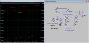
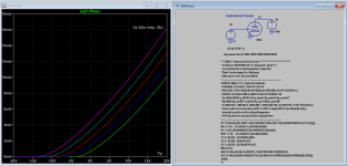
Attached grid drive current sim comparision with another project.
I notice an 700mA inrush of grid current, 0.1u in cathode has removed it.
Yes.
To monitor the grid drive voltage you can hook the scope to the 1 ohm (or more) resistor in the cathode and ground. If your HV is 25KV, then you'll need +-20V swing, but even with this drive level is probably ok when the HV in 7-8KV, it'll drive to full output either way you will not over drive the output.
Attached grid drive current sim comparision with another project.
I notice an 700mA inrush of grid current, 0.1u in cathode has removed it.
Attachments
Last edited:
That's good to see another using the 6BK4 in a pulse circuit.
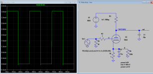
Is the addition of the 0.1uf cap on the cathode what lowered the voltage of the pulldown voltage?
Previously I saw 700V, the latest graph shows about 200V.
Is the red line showing grid Current?
Is most of that thru the 50Ω or can that much current flow into the Grid? (measured thru the 1Ω resistor).
Thanks, Mikek
P.S.
The first thing I saw was the 6BK4 spec sheet, it only shows negative voltages that pinch the tube into no conduction. But even in conduction the
grid voltage never goes positive, I'm assuming this positive voltage gives higher conduction?
I changed Trise from 1us to 0.1us, the 700mA pulse has dissappeared, so look like it's the rise time is too large (slow) that causes the pulse to show up.
The grid current drawn is mostly when it's positive going, that is normal. In Hi-Fi amp this is called A2 Class amp.
Is the addition of the 0.1uf cap on the cathode what lowered the voltage of the pulldown voltage?
Is only 4-30Hz, 0.1u is negligible, if you do see spike you can try to filter it.
The grid current drawn is mostly when it's positive going, that is normal. In Hi-Fi amp this is called A2 Class amp.
Is the addition of the 0.1uf cap on the cathode what lowered the voltage of the pulldown voltage?
Is only 4-30Hz, 0.1u is negligible, if you do see spike you can try to filter it.
Attachments
Last edited:
Hmm, my function generator is supposed to have a 120ns risetime.
Not sure how that falls into your above comment.
Mikek
Not sure how that falls into your above comment.
Mikek
I'd like someone to expound on my question below.
I don't doubt it works as other have suggested the same, it just doesn't jive the with tube curves.
The first thing I saw was the 6BK4 spec sheet, it only shows negative voltages that pinch the tube into no conduction. But even in conduction the
grid voltage never goes positive on the tune curves, I'm assuming this positive voltage gives higher tube conduction?
Thanks for clarifying, Mikek
Looking to purchase an anode connector for a 6BH4 tube.
Ebay seems to $20 to $30, seems ridiculously priced, but I never shopped for one.
Any suggestions?
Thanks, Mikek
Ebay seems to $20 to $30, seems ridiculously priced, but I never shopped for one.
Any suggestions?
Thanks, Mikek
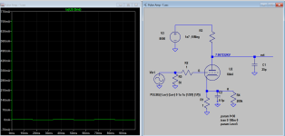
It takes me a few days to answer the same question you ask 2 days ago. Here is expanded curve so you can see better. The original stop at zero, let everyone speculates beyond that, but with the help of model we hope we can predict it, and confirm in practical work. There are many amps such as 300B does not have curve beyond zero, yet they work ok in A2 mode. Because we deal with pulse then there is even less burden with tube in A2 mode. Others can jump in to expand further.
Attachments
Last edited:
Try here. https://www.tubesandmore.com/products/grid-plate-anode-cap-ceramic-tubes
May also have to fish around the site if that link does not work.
May also have to fish around the site if that link does not work.
I found a 6.3V filament transformer, my tube spec is 200ma. I loaded the transformer with 31.5Ω to simulate the tube heater, the Voltage is 8V.
(8.7V open circuit). How do you guys deal with to high heater voltages?
An 8Ω resistor gets it down to 6.4V with 124.1 V on the transformer input.
Thanks Mikek
(8.7V open circuit). How do you guys deal with to high heater voltages?
An 8Ω resistor gets it down to 6.4V with 124.1 V on the transformer input.
Thanks Mikek
Last edited:
A couple of things to consider, assuming the transformer is in a good working condition:I found a 6.3V filament transformer, my tube spec is 200ma. I loaded the transformer with 31.5Ω to simulate the tube heater, the Voltage is 8V.
(8.7V open circuit). How do you guys deal with to high heater voltages?
An 8Ω resistor gets it down to 6.4V with 124.1 V on the transformer input.
Thanks Mikek
1) The transformer is designed to supply a big current, therefore 200mA is not loading it at all.
2) The primary is rated for 110V, but you got 124V. What is the nominal primary voltage for the transformer?
Probably a combination of 1&2.
Usually you just put a resistor to drop the voltage, exactly as you have done.
Yes, it is designed for 800ma, although it is physically small.A couple of things to consider, assuming the transformer is in a good working condition:
1) The transformer is designed to supply a big current, therefore 200mA is not loading it at all.
2) The primary is rated for 110V, but you got 124V. What is the nominal primary voltage for the transformer?
Probably a combination of 1&2.
Usually you just put a resistor to drop the voltage, exactly as you have done.
Our Voltage here runs a little high, I can't find specs on the transformer.
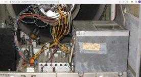
I visited the local Ham club to look thru the junque pile for a transformer,
I haven't been for several years, new leadership, disposed of most of the
junque. I did find a Heathkit VTVM in poor shape, pulled up the manual and found it had a 6.3V transformer.
I paid $5 for the VTVM so I have the transformer, and a couple of nice 10 turn pots.
How critical is heater voltage?
I note, if I set it a 6.3V on 124V input and drop the input to 120V, it is now 6.1V.
Thanks, For the help on my first tube project.
Mikek
Well, I'd say +/- 5%, but many tubes specify around +/- 10% maximum deviation. 6.1V is pretty close to 6.3V, you are fine.How critical is heater voltage?
I'm using a 6BK4C, it is a leaded glass tube, should I still put it in a cage to prevent radiation exposure?
I'm running high voltages 8kv, maybe higher later.
If so, what material, space between cage and tube, i.e. how do I build it?
Thanks, Mikek
I'm running high voltages 8kv, maybe higher later.
If so, what material, space between cage and tube, i.e. how do I build it?
Thanks, Mikek
You'll need a shield for shock hazard prevention anyhow so you can use the same shield to add to to X ray radiation reduction. Many just recommend a simple shield, a steel cage as early colour TV. This article may help to decide on what material to use. You'll need a X radiation meter or GM (Geiger-Mueller) instruments, to verify against tube in use the level in tube specs and after added the shield.
https://www.jstage.jst.go.jp/article/jrr1960/5/3-4/5_3-4_147/_pdf
https://www.jstage.jst.go.jp/article/jrr1960/5/3-4/5_3-4_147/_pdf
Attachments
Elsewhere it was suggested at 8kV the hazard is much reduced from the 25kV that TV's used to run.
However, as you say, HV protection and I also want physical protection of the tube.
I walked through my local scrap yard yesterday and found a 3" pipe with 0'2: walls that I will cut/mill ventilation
slots in for air flow.
I have another problem, which may be out of scope for this group, but, I'll ask. It pertains to primary to secondary isolation and possible internal arcing/leaking of the neon sign transformer.
I have now hit a point where I think I have a problem where I am putting one side of the neon sign transformer secondary at ground potential.
The scenario is using a sig gen to drive the tube grid, this ties the HV PS at ground (near) potential though the circuit breaker box (sure would be nice to know if the neon transformer could handle that).
I have made a drawing showing in red how the neutral/ground bond causes this to happen.
https://www.dropbox.com/s/kjut0dl8j28q3se/Pulser Push-pull design.Neutral ground problem.jpg?dl=0
Can I opto isolate the drive signal from the sig gen to isolate the ground?
Is there another way around this?
Thanks, Mikek
Maybe you can use an isolation transformer on neon transformer or both so that the secondary of the isolation transformer is not grounded (floating), but can still be grounded via a AC capacitor while DC path and everything else is unaffected. In other word the ground can be broken just like opto coupler.
Last edited:
- Home
- Amplifiers
- Tubes / Valves
- HV Pulse amplifier help 6BK4