I had someone else look at and tweak the circuit.
Here's what he did. I'd be interested to know if you think he pushed the tube to hard.
https://www.dropbox.com/s/esci7na1lbpa82s/Tube_Pulser_JL_1.zip?dl=0
And then he added a push-pull version. (he didn't show the wave form) I may just have download LTspice just to see it.
https://www.dropbox.com/s/6d1csywqihhulx9/Tube_Pulser_JL_pp1.zip?dl=0
Mikek
https://www.diyaudio.com/community/threads/hv-pulse-amplifier-help-6bk4.399314/
Could you identify and ask Moderator to move posts of your project to above threads, please.
Could you identify and ask Moderator to move posts of your project to above threads, please.
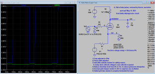
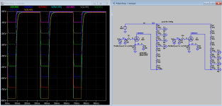
FYI in relation to using 6bk4 model as pulse amp:
Below is output pulse waveform, when f is frequency of operation:
This gives symmetry waveform
PULSE(0 6 0 1u 1u {1/2/f} {1/f})
This gives asymmetry waveform
PULSE(0 6 0 1u 1u {1/4/f} {1/f})
In other word it is very easy to change pulse width or duty circle. Or build 555 timer.
Below is output pulse waveform, when f is frequency of operation:
This gives symmetry waveform
PULSE(0 6 0 1u 1u {1/2/f} {1/f})
This gives asymmetry waveform
PULSE(0 6 0 1u 1u {1/4/f} {1/f})
In other word it is very easy to change pulse width or duty circle. Or build 555 timer.
I had someone else look at and tweak the circuit.
Here's what he did. I'd be interested to know if you think he pushed the tube to hard.
https://www.dropbox.com/s/esci7na1lbpa82s/Tube_Pulser_JL_1.zip?dl=0
And then he added a push-pull version. (he didn't show the wave form) I may just have download LTspice just to see it.
https://www.dropbox.com/s/6d1csywqihhulx9/Tube_Pulser_JL_pp1.zip?dl=0
Mikek
Here's what he did. I'd be interested to know if you think he pushed the tube to hard.
https://www.dropbox.com/s/esci7na1lbpa82s/Tube_Pulser_JL_1.zip?dl=0
And then he added a push-pull version. (he didn't show the wave form) I may just have download LTspice just to see it.
https://www.dropbox.com/s/6d1csywqihhulx9/Tube_Pulser_JL_pp1.zip?dl=0
Mikek
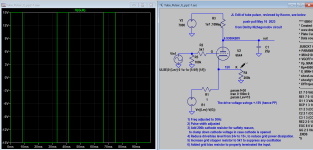
See attached snapshot of my reviews as requested. As this is switching amp, power dissipation is not a big problem but I think better to limit the peak current to 2mA or as recommended in the specs. The same apply to grid drive current. The tweak PP is a good one, does away with the need for active device, but cathode resistor or zener still require for safety purpose. In practice not sure how PP tweak is done.
Attachments
As I have said, I have not seen JL's schematic, but I trust that your modeling shows improvements using your schematic.
Note: we expect to go as low as 4Hz, if that makes any difference in the circuit and may test to the frequency limit of the circuit.
If you were building, would you go with the push-pulls circuit or the single sided?
Thanks, Mikek
Note: we expect to go as low as 4Hz, if that makes any difference in the circuit and may test to the frequency limit of the circuit.
If you were building, would you go with the push-pulls circuit or the single sided?
Thanks, Mikek
The tweak with PP is fine, but can very well be achieved by shifting the bias to just -5v, so a 5v pulse will swing between -5v and 5v a total of 10v (doubling the pulse height). This is as simple as it can get and probably more reliable, you know where I would put the money on.
Attachments

Thanks Dmitry,
I have a B&K Function Generator coming. It will put out a 10V pp pulse, and I can DC offset that for a ±5vpp input signal.
Is that what you describe? So, no need for ±15Vpp?
Thanks, Mikek
I have a B&K Function Generator coming. It will put out a 10V pp pulse, and I can DC offset that for a ±5vpp input signal.
Is that what you describe? So, no need for ±15Vpp?
Thanks, Mikek
Ya, the negative 5v offset (measure first) from function generator is fine to bias the tube. No need.
Couple questions, Is R2 (1Ω) needed or is that just to make spice work?
What about R1?
I'm thinking it may be needed, but not sure why the cathode can't go to ground?
Thanks, Mikek
What about R1?
I'm thinking it may be needed, but not sure why the cathode can't go to ground?
Thanks, Mikek
Hi Dmitry,
Note: 5 says, Increase grid stopper resistor to 5k1 to suppress oscillation" bu the schematic shows it as 100K.
What value should it be?
https://www.dropbox.com/s/uxwetsrwc9v2lxt/Pulser Push pull as Revised by Dmitry.jpg?dl=0
Thanks, Mikek
Note: 5 says, Increase grid stopper resistor to 5k1 to suppress oscillation" bu the schematic shows it as 100K.
What value should it be?
https://www.dropbox.com/s/uxwetsrwc9v2lxt/Pulser Push pull as Revised by Dmitry.jpg?dl=0
Thanks, Mikek
1) R1, 1 ohm will help to limit the short circuit current in case of tube breakdown and hence limit damage, is normal practice.
2) R2, 1 ohm is grid stopper, can increase up to 5k1 if necessay to suppress oscillation. The tube has gain over 2000, so it's necessary to take precaution prevent oscillation.
3) 100k is grid bias resistor, can be adjust to suit the input device output impedance. Say if function generator is 50 ohms you may want to reduce it to 50 ohms for best match while still valid as grid bias resistor.
Btw I'm Koonw not Dmitry, he is the Paint Tool model software creator of our tube model.
Last edited:
Ahh! Thanks Koonw.
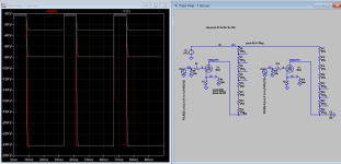
It looks like you have the ability to run LTspice, I need a different load attached with the waveforn in each load. I'm sure they will be a little bit different which is OK, but hopefully not a lot different. Here's the scenario, We want to run 4 experiments at about 1kVm 2kV, 3Kv, and 4kV, the another 4 at 5kV, 6kV, 7kV and 8kV. we are adding a voltage divider string of eight 1.5MΩ resistors. The first vessel will have 1kV and the load is 25pf. the 2nd, 2kV and 25pf load, etc.
Then a second test with 25pf load at 4kV, 25pf load at 5kV, etc. This drawing shows the first test, the second test will just shift all the vessels to the right, for the 5, 6, 7 and 8kV test.
Mikek
https://www.dropbox.com/s/qstoeysxt... with Banana Connectors with vessels.jpg?dl=0
Koonw, I want to apologize, It's seems you were the one doing most of the modeling and it was Dmitry that developed the subckt.
I can't seem to figure it all out after the many posts were moved from the other thread, anyway sorry for mis-identifying you.
Well you surprised us, (my son and I).
I was thinking the 10MΩ would still be in the circuit. But I see it is not needed, (or wanted!).
I'm confused by the 8kV at the bottom of the graph, I saw from the model with just a 10MΩ and 25pf, that
there was a bit of a slope as the 25pf was charged by the 10MΩ, Also the graph went from 0V up to 8kV,
when the pulse was rising to 8kV it would slope because of the RC time constant, the fall time was much faster.
I understand we are doing a negative pulse, but, I would understand better if you made it a positive pulse from 0V up to 8kV.
In the writing of this and checking back and forth with the graph, the slope of the waveform finally clicked with me.
If you would could you turn it around.
We could adjust the resistive divider to get the voltages a little closer at each vessel, but, I think they are close enough,
for the 2 sets of tests to answer our question.
The question is, Does higher voltage increase our result linearly and is there a point of diminishing returns.
Thanks for the help. Mikek
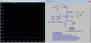
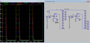
I have inverted the plot, no change in actual sch.
The question is, Does higher voltage increase our result linearly and is there a point of diminishing returns.
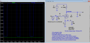
Does not appear to be the case. It appears the timing constant dominated the result (linearity), which does not improve with increasing HV. To sim HV 25KV, the pulse is increased to 20V and bias to -20V
The question is, Does higher voltage increase our result linearly and is there a point of diminishing returns.
Does not appear to be the case. It appears the timing constant dominated the result (linearity), which does not improve with increasing HV. To sim HV 25KV, the pulse is increased to 20V and bias to -20V
Attachments
Sorry, I meant the results of the experiment we are doing where we use the different high voltages.
The waveform change is interesting, previously with a 10MΩ and 25pf load the risetime had the typical R charging C slope,
now we have a falltime the has a c discharging through R slope.
The slopes are fast compared to our vessel reaction. so they are not a problem.
Thanks, Mikek
The waveform change is interesting, previously with a 10MΩ and 25pf load the risetime had the typical R charging C slope,
now we have a falltime the has a c discharging through R slope.
The slopes are fast compared to our vessel reaction. so they are not a problem.
Thanks, Mikek

- Home
- Amplifiers
- Tubes / Valves
- HV Pulse amplifier help 6BK4