Maybe you can use an isolation transformer on neon transformer or both so that the secondary of the isolation transformer is not grounded (floating), but >can still be grounded via a AC capacitor while DC path and everything else is unaffected. In other word the ground can be broken just like opto coupler.
Hmm, I look more into the isolation transformer, that would be plug and play vs, adding a opto isolator and building a LV PS. (I'm not even sure a opto has a high enough isolation voltage)
Thanks, Mikek
I received other feedback, the neon transformer is Center Tapped for a connection to ground.
If I only use one side of the Neon T, that will be fine, however that is not a high enough voltage, so then I add a Voltage doubler.
This seems to be the simplest and cheapest route for me at this time.
Thanks, Mikek
PS, that article on 6BK4 radiation and shielding is very interesting.
If I only use one side of the Neon T, that will be fine, however that is not a high enough voltage, so then I add a Voltage doubler.
This seems to be the simplest and cheapest route for me at this time.
Thanks, Mikek
PS, that article on 6BK4 radiation and shielding is very interesting.
Or so I thought! I've been looking at capacitors, for a doubler I need about 0.02uF at 5kV, getting expensive.This seems to be the simplest and cheapest route for me at this time.
I may make it a quadrupler so I can use lower voltage capacitors, 3kV.
Maybe you like the idea described in this article: https://woelen.homescience.net/science/physics/misc/larger-psu.html
https://www.wccdusa.com/neon-transformers-core-and-coils
One way make the neon transformer safe is to derate the transformer and series 2 or more to increase secondary voltage. Usually it should have a ground shield and double bobbin to be really safe.
https://www.wccdusa.com/neon-transformers-core-and-coils
One way make the neon transformer safe is to derate the transformer and series 2 or more to increase secondary voltage. Usually it should have a ground shield and double bobbin to be really safe.
Last edited:
I sent a message the wccdusa asking about there transformers.
I did find this doubled that I think solves the Neutral/Ground issue.
It uses the neon sign CT as the HV ground.
https://www.dropbox.com/s/c4t13kzi62txwqo/Centertapped Doubler.jpg?dl=0
I hope this is getting me what I want!
Thanks, Mikek
I did find this doubled that I think solves the Neutral/Ground issue.
It uses the neon sign CT as the HV ground.
https://www.dropbox.com/s/c4t13kzi62txwqo/Centertapped Doubler.jpg?dl=0
I hope this is getting me what I want!
Thanks, Mikek
Last edited:
Seems like a flyback circuit would be easier and safer than neon transformers and voltage multipliers. In my younger days I tried to connect the secondaries from two neon transformers in series but it never produced any arcs.
Yes to the flyback, but I don't want to build one and so far I haven't found 120V input 8 or 10kV output.
Possibly you had tthe transformers out of phase and they cancelled?
I get plenty of arc out of a 9kV, but at one time I had a 30kV neon transformer
and I could draw arcs out of the dirt on the ground!
Mikek
Possibly you had tthe transformers out of phase and they cancelled?
I get plenty of arc out of a 9kV, but at one time I had a 30kV neon transformer
and I could draw arcs out of the dirt on the ground!
Mikek
I have the 6BK4 Pulser just about built, the power supply is separate and I'm waiting for some parts.
When I'm ready to do the first power up, I want to start with low voltage, How low can I make the B+
for a 6BK4 and still get results that would tell me it is working. Will 160 Volts be enough? I have that
already available. The design I'm using is below.
When I'm ready to do the first power up, I want to start with low voltage, How low can I make the B+
for a 6BK4 and still get results that would tell me it is working. Will 160 Volts be enough? I have that
already available. The design I'm using is below.
Attachments
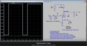
Hi all I have the following circuit.

I have applied a 150V B+ and have a squarewave input to drive the grid of +2V, -10V.
The output is a 48V pulse riding on top of 60Vdc.
I can go more positive on the grid, but it makes no difference on the output waveform DC level.

The plan is go to 8kV.
Is 150V B+ enough to make this circuit act the way it will at 8kV?
Any ideas why I have the DC level on the output?
I would experiment with higher voltages to see is I stay at a 60 V DC level, but I'm waiting for parts.
Thanks, For your input, Mikek
I have applied a 150V B+ and have a squarewave input to drive the grid of +2V, -10V.
The output is a 48V pulse riding on top of 60Vdc.
I can go more positive on the grid, but it makes no difference on the output waveform DC level.
The plan is go to 8kV.
Is 150V B+ enough to make this circuit act the way it will at 8kV?
Any ideas why I have the DC level on the output?
I would experiment with higher voltages to see is I stay at a 60 V DC level, but I'm waiting for parts.
Thanks, For your input, Mikek
Tube is saturated if more positive drive makes no difference. What is current? You're obviously not applying the 150V through 10 megohms.
I have it running on 6kV, 2.5MΩ dropping resistor and 4.5MΩ load.
That voltage divider gives me 3,844V on the plate. When the grid is driven,
I get a 3,678V pulse on top of 166Vdc.
I'll up the voltage when I get all my parts.
Thanks, Mikek
That voltage divider gives me 3,844V on the plate. When the grid is driven,
I get a 3,678V pulse on top of 166Vdc.
I'll up the voltage when I get all my parts.
Thanks, Mikek
Hi Koonw,I changed Trise from 1us to 0.1us, the 700mA pulse has dissappeared, so look like it's the rise time is too large (slow) that causes the pulse to show up.
The grid current drawn is mostly when it's positive going, that is normal. In Hi-Fi amp this is called A2 Class amp.
Is the addition of the 0.1uf cap on the cathode what lowered the voltage of the pulldown voltage?
Is only 4-30Hz, 0.1u is negligible, if you do see spike you can try to filter it.
I hope you are still lurking, I finally got the tube pulser circuit all together. I don't like the waveform I'm getting.
Two things, the waveform sags during the pulse, I suspect not enough filter capacitance in the Power Supply. Ahh, I think I confirmed that,
I just raised the frequency 10X and the sag is gone. The other thing is a large negative pulse when the tube turns off. I think you may have referred to
this in your comment. So, I saw you it a cap across the 1Ω resistor, is that what you mean by filtering it?
I did note the negative pulse is a bit reduced when I 10Xed the frequency. Don't know what the means
I have attached a drawing of the approximate setup and a picture of the actual boxes connected.
Modular build for other uses. Also scrapped enclosures. (Frugal build) 🙂
I'm a little concerned about adding filter capacitors to my DC supply, it is a flyback type supply that I have almost zero data on! Three pots, I found one is the voltage adjust, haven't figured out the others. Link to my DC supply, 5kV to 30kV. https://www.ebay.com/itm/313119408064?var=611839114175
Note: the scope waveform is at 4 Hz, I'm no longer concerned about the sag, I am concerned about the negative pulse.
Thanks for your input, Mikek
Sounds like the scope probe does not give accurate response to square wave, have you calibrate it?
The cap on the cathode has effect only if the Trise (rising time) of the input if too low, as this create spike that will be will be shunted by the cap.
The cap on the cathode has effect only if the Trise (rising time) of the input if too low, as this create spike that will be will be shunted by the cap.
Last edited:
It could be inductance in your sense resistor,or the wiring, I would measure at the cathode resistor of the 6BK4 for the waveform.
The negative pulse is much, much less, (relative to the rest of the signal) but I don't get much signal across a 1Ω resistor, so, the signal is not clean and barely one division.
Any negative effect of changing it to 100Ω just for testing purposes?
Thanks Mikek
Any negative effect of changing it to 100Ω just for testing purposes?
Thanks Mikek
What is the grid resistor value, use 50 ohms if the sig gen is 50ohms, this should reduce distortion due to mismatching impedance. You can use 100 cathode resistor, the DC raised about 1V, introduce more local feedback that can reduce distortion too.
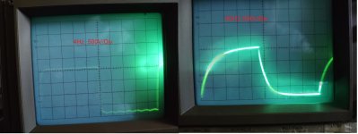
OK, terminating the function generator and putting in a 100 cathode resistor did remove the negative pulse.
Photos below. I think the noise on the waveform is PS ripple at 68kHz.

I also got brave and put a 10 to 1 resistor on the 2kV output and looked at it with my scope.
4Hz is great, 40Hz, not so good. But it looks like everything is working, any suggestions on how to make the risetime faster?
Now all we need to do is test how quickly the DC pulse breaks up an emulsion compared to 60Hz ac.
Thanks, Mikek

Photos below. I think the noise on the waveform is PS ripple at 68kHz.
I also got brave and put a 10 to 1 resistor on the 2kV output and looked at it with my scope.
4Hz is great, 40Hz, not so good. But it looks like everything is working, any suggestions on how to make the risetime faster?
Now all we need to do is test how quickly the DC pulse breaks up an emulsion compared to 60Hz ac.
Thanks, Mikek
Attachments
But it looks like everything is working, any suggestions on how to make the risetime faster?
It appears there is a lot of stray capacitance (few hundred) in the output, the frequency response due to Millet effect will multiply this capacitance some more if stray capacitance in the input. So maybe lift the resistor divider pad higher and try another input cable see if that frequency response improved. Else try to reduce the load..
It appears there is a lot of stray capacitance (few hundred) in the output, the frequency response due to Millet effect will multiply this capacitance some more if stray capacitance in the input. So maybe lift the resistor divider pad higher and try another input cable see if that frequency response improved. Else try to reduce the load..
While testing I changed my Function Generator from squarewave to sinewave and get a nice 8kV DC sinewave. The Function Generator has a DC Offset that helps set the sinewave close zero. Now that I see I have a frequency control and we are no longer stuck with only 60Hz high voltage, How can I remove the DC component and just have an AC signal driving my resistive divider? Is it as simple as putting in a series capacitor? I can parallel 10-2200pf caps for 22nF, 650kΩ at 11 hz. driving the 12kΩ resistive divider.
Or do I need to build a second circuit and do push pull to get an AC sinewave?
Thanks, Mikek
Or do I need to build a second circuit and do push pull to get an AC sinewave?
Thanks, Mikek
- Home
- Amplifiers
- Tubes / Valves
- HV Pulse amplifier help 6BK4