OK read through the thread and I'll be fine with 6.3V filament supply as I wont be using 12V tubes. The HV rail does need a centre tap.
NO, can use 6.3v for tube 12V
158-0-158VAC for the HV supply? (to get 220VDC)
SO you can use 158+158 = 316VAC for HV
you need use R7 = 1K/5W
and all cap need 450V
thanks
Quanghao, I looked at all the schematic and it does not have a B+ value. What is the required B+?
Ok, I see, for 6DJ8 the B+ is 220vdc, is this correct?
Yes. All tube 6dj8 . You need low voltagle. 200 to 220 vdc.
Thanks
Quanghao,
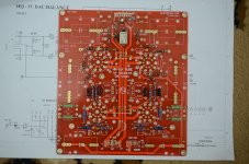
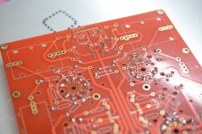
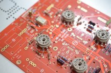
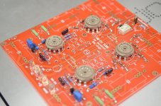
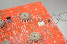
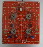
My PCBs have arrived. Thankyou - they're very good quality.
I understand that you can use all 12au7, all 6dj8, or a mixture of 12au7 input and 6j8 output. Why would I choose one of those options over another? Is there a single recommended option?
I haven't been able to find a standard transformer with a 158V secondary. Do you have any standard transformer part numbers?
Cheers,
Jon
Quanghao,
My PCBs have arrived. Thankyou - they're very good quality.
I understand that you can use all 12au7, all 6dj8, or a mixture of 12au7 input and 6j8 output. Why would I choose one of those options over another? Is there a single recommended option?
I haven't been able to find a standard transformer with a 158V secondary. Do you have any standard transformer part numbers?
Cheers,
Jon
Yes, you can use option of me like : All tube 12Au7
158V , it only use for all tube 6dj8.
No. i now i not have it.
thanks
Jon don't forget you can connect twin transformer secondaries in parallel to double the output in volts but halve the current.
So a 2 x 0 - 80V transformer can be wired to give 0 - 160V before rectification.
So a 2 x 0 - 80V transformer can be wired to give 0 - 160V before rectification.
Attachments
Last edited:
Thanks. I'll keep my eye out for suitable transformers. By my calculations, I need about 190VAC input for a 260V B+ to suit an all 12au7 configuration. So I'm also looking for 95V secondaries.
Yes, you can use option of me like : All tube 12Au7
158V , it only use for all tube 6dj8.
No. i now i not have it.
thanks
Why did you use 12au7 rather than 6dj8?
One custom hand made toroid arrived. Should be enough headroom to handle the current draw. The HV rail draws 100mA and the heater supply draws 1.2A, so I have 158.2VAC @ 200mA and 12VAC @ 2Amp
Jon - if you are still considering getting the Buffalo then do some reading on running the ES9018 chip in current and voltage mode - it likes to see 39R I/V but on Quanghau's page here (scroll down a third of the page) he mentions it sound great with 10R i/v and even no I/V resistors to run in voltage mode. 10R gives 1.4V RMS output.
It might be worth getting a few values of standard resistors and trialling before committing to audiophile brands.
Attachments

Why did you use 12au7 rather than 6dj8?
yes. the sound all 12au7 it is nice than 6dj8. 6dj8 the sample solist .
me and my friend not like .
One custom hand made toroid arrived. Should be enough headroom to handle the current draw. The HV rail draws 100mA and the heater supply draws 1.2A, so I have 158.2VAC @ 200mA and 12VAC @ 2Amp
passive420, where did you have this toroidal trafo custom made?
adeveza - this was made by Terry Monaghan of Canterbury Windings here in England. Hands down one of the finest toroid makers in the country. His audio grade trafos are practically works of art.
There is nothing out there off the shelf that will provide dialled in secondary voltages in such a compact form, so custom made it was. I really didn't fancy using 110V secondaries for instance and wasting / dissipating 60 volts across the regs.
Definitely enquire around some US toroid makers for quotes, there are superb manufacturers over there, Avel Lindberg springs to mind. Get an electrostatic screen between windings and a GOSS band if possible.
Last edited:
One custom hand made toroid arrived. Should be enough headroom to handle the current draw. The HV rail draws 100mA and the heater supply draws 1.2A, so I have 158.2VAC @ 200mA and 12VAC @ 2Amp
Jon - if you are still considering getting the Buffalo then do some reading on running the ES9018 chip in current and voltage mode - it likes to see 39R I/V but on Quanghau's page here (scroll down a third of the page) he mentions it sound great with 10R i/v and even no I/V resistors to run in voltage mode. 10R gives 1.4V RMS output.
It might be worth getting a few values of standard resistors and trialling before committing to audiophile brands.
Thanks for the tip regarding the IV resistors.
I'm afraid I'm still a little confused about tube choice and transformer specs. What made you go with 6DJ8 rather than 12AU7?
Does your transformer have a centre tap on the HV secondary, i.e. is it 158-0-158, or just 0-158? If I were to go with 12AU7, do I need to have a 12.6V secondary for the filament supply? What would my HV secondary need to be - I worked it out to be 186V, but would appreciate confirmation.
Cheers,
Jon
[QUOTE=jonwhitear;
Hi!
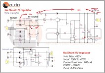
Ưith 158+158VAC ~ 400VAC
the voltage across R7 = 50 to 60V. So you need to increase the R7 up to 1.5K 1k / 5W
The voltage across IRF840 = 50 -100V. Output = 260V
And Heat-connect 12VDC, please see image
All tube 12Au7 i love the sound, so you can try to test if you like 6DJ8 ouputs
Thanks
Hi!
Ưith 158+158VAC ~ 400VAC
the voltage across R7 = 50 to 60V. So you need to increase the R7 up to 1.5K 1k / 5W
The voltage across IRF840 = 50 -100V. Output = 260V
And Heat-connect 12VDC, please see image
All tube 12Au7 i love the sound, so you can try to test if you like 6DJ8 ouputs
Thanks
Attachments
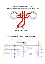
Thanks quanghao - your diagrams make it clearer. I understand that I can use a 12V secondary for the filament supply, regardless of whether I'm using a 12V or 6V tube.
I'm still a little confused about the HV supply. Your diagram seems to suggest I need 320VAC input to deliver 260V B+. If so, what secondary should I have on my transformer to provide 320VAC input?
Cheers,
jon
I'm still a little confused about the HV supply. Your diagram seems to suggest I need 320VAC input to deliver 260V B+. If so, what secondary should I have on my transformer to provide 320VAC input?
Cheers,
jon
jonwhitear; I'm still a little confused about the HV supply. Your diagram seems to suggest I need 320VAC input to deliver 260V B+. If so said:yes, 158+158 of your transformer!
thanks
Thanks for the tip regarding the IV resistors.
I'm afraid I'm still a little confused about tube choice and transformer specs. What made you go with 6DJ8 rather than 12AU7?
Does your transformer have a centre tap on the HV secondary, i.e. is it 158-0-158, or just 0-158? If I were to go with 12AU7, do I need to have a 12.6V secondary for the filament supply? What would my HV secondary need to be - I worked it out to be 186V, but would appreciate confirmation.
Cheers,
Jon
186V is correct Jon.
I am an idiot and didn't correct my post. I see that 0 - 158V is fine for 220V rails.
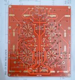
Looking at the board I thought there was a centre tap requirement - there is a middle pad at the HV supply input for CT or dual secondaries if needed. This would set them in parallel giving an 0 - xxxV but with double the current capability, if you get me... The schematic shows 0-V rails only.
So your 0 - 186VAC will do the job for 260V HV supply.
12VAC secondaries will give us 16VDC after rectification so plenty of headroom (and not too much dissipation) to get 12.3VDC filament supply.
- Status
- Not open for further replies.
- Home
- Group Buys
- HQ-IV tube output balance DAC