I bought in a local store 1008 SMT package 1 micro inductors declared as ceramic core. But they are attracted to magnet so I think that core are ferrite.
Soldering pads on PCB are for 1210 package but at Mouser I was not able to find any similar to original HPS 5.1 picture. What would happen with magnetic core inductors in circuit?
Fasterbyelan, what input inductors do you use?
Bought from RS Components here in the UK - http://uk.rs-online.com/web/cpd/0135204/?searchTerm=135204
Unfortunately they have been discontinued. This may be a suitable replacement - 744760310C | Wurth WE-KI Series Wire-wound SMD Inductor with a Ceramic Core, 1 μH 5% Wire-Wound 150mA Idc Q:23 | Wurth Elektronik
And I don't know the difference between ceramic and ferrite core inductors but I'm going to find out!
Last edited:
Z is the input resistance of the amplifier ie the cartridge load - apologies if this was misleading.
Ok, I understand now, then why leaving the input open? With a high input impedance, it will be extremely sensitive to any perturbations. What you see as wildly swinging between rails is not necessary "instability" but could be very well the result of the 47k shot noise, combined with the amp own 1/f noise and thermal gain fluctuations, saturating the whole amp (if I'm reading correctly the schematic, LF gain is 80dB, right?).
I don't think leaving the input open matches any possible real world use case.
This is what I've done to cure the oscillating problem when the input was left open circuit or set at 47K for a MM cartridge.
I removed all the fets and measured the IDSS which were on the high side.
I did read somewhere that the high IDSS was causing the fets to saturate and this is what’s causing it to oscillate.
Decreasing the drain resistor R201 100R (2 watt) to 95R now it working fine.
I removed all the fets and measured the IDSS which were on the high side.
I did read somewhere that the high IDSS was causing the fets to saturate and this is what’s causing it to oscillate.
Decreasing the drain resistor R201 100R (2 watt) to 95R now it working fine.
Msdin, which input inductors do you use in your phono preamp?
I'm not sure as I was given it as an unfinished project and the inductors were already fitted.
These look like the one fitted I'll have a look if I have a parts list.
http://uk.farnell.com/wurth-elektronik/74476401/inductor-1uh-10-0-4a-120mhz/dp/2471622
Sharif.
Last edited:
Im sorry for asking this without the schematic in front of me but wouldn't decreasing the value of the 100R resistor increase the IDSS?
This is what I've done to cure the oscillating problem when the input was left open circuit or set at 47K for a MM cartridge.
I removed all the fets and measured the IDSS which were on the high side.
I did read somewhere that the high IDSS was causing the fets to saturate and this is what’s causing it to oscillate.
Decreasing the drain resistor R201 100R (2 watt) to 95R now it working fine.
I'm not sure as I was given it as an unfinished project and the inductors were already fitted.
These look like the one fitted I'll have a look if I have a parts list.
74476401 - WURTH ELEKTRONIK - Surface Mount High Frequency Inductor, WE-GF Series, 1 µH, ± 10%, 1210 [3225 Metric], 120 MHz | Farnell element14
Sharif.[/QUOTE
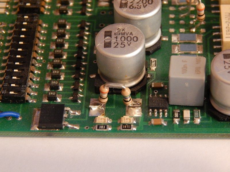
They are ferrite core inductors. Ceramic core have much higher DC resistance (longer wire).
Im sorry for asking this without the schematic in front of me but wouldn't decreasing the value of the 100R resistor increase the IDSS?
No. A drain resistor changes only Vds. What msdin suggested is sensible: if the Idss was on the high side, any input perturbation may saturate the input stage, which in turn breaks the feedback loop, hence the thing starts to oscillate.
This is what I've done to cure the oscillating problem when the input was left open circuit or set at 47K for a MM cartridge.
I removed all the fets and measured the IDSS which were on the high side.
I did read somewhere that the high IDSS was causing the fets to saturate and this is what’s causing it to oscillate.
Decreasing the drain resistor R201 100R (2 watt) to 95R now it working fine.
Thanks for that, I will give it a go once I get some resistors. It makes a substantial reduction in the power across R201 which can't be a bad thing!
I assume the noise present at the i/p with it set to 47K and/or nothing connected is leading to the FET's saturating. The reduction in current through makes them less sensitive.
Ok, I understand now, then why leaving the input open? With a high input impedance, it will be extremely sensitive to any perturbations. What you see as wildly swinging between rails is not necessary "instability" but could be very well the result of the 47k shot noise, combined with the amp own 1/f noise and thermal gain fluctuations, saturating the whole amp (if I'm reading correctly the schematic, LF gain is 80dB, right?).
I don't think leaving the input open matches any possible real world use case.
You should be able to change i/p connections whilst powered (to fit a different cartridge for example) without the amp self destructing IMO. However as I have only recently started using the 47K i/p load, I may need to change how I use the amp ie switch it off!
The reply above from msdin explains the reason for the issue. Looking back in this thread, the designer did suggest the same modification, see here
And whilst the LF gain is 80dBs at the output, I'm measuring at the head amp output which is x40
You should be able to change i/p connections whilst powered (to fit a different cartridge for example)
I guess it's a matter of habits. Me, I'm powering down my NAD power amp when messing with the RCA input cables, even if I know it won't destroy the speakers or the amp itself. I would definitely not mess with the cartridge while the whole gain chain is on, but then what do I know?
Hello
I want to build the phono preamp HPs5.1 with the extra filter board. I'm looking for the pcb files but these pcbs are not available on the original web site of the designer . Does someone has these files , pcb (gerber), schematic, bom ? Or knows where to find them ? Thanks in advance for your help !! Kinds regards from France 🙂
I want to build the phono preamp HPs5.1 with the extra filter board. I'm looking for the pcb files but these pcbs are not available on the original web site of the designer . Does someone has these files , pcb (gerber), schematic, bom ? Or knows where to find them ? Thanks in advance for your help !! Kinds regards from France 🙂
Hello
I want to build the phono preamp HPs5.1 with the extra filter board. I'm looking for the pcb files but these pcbs are not available on the original web site of the designer . Does someone has these files , pcb (gerber), schematic, bom ? Or knows where to find them ? Thanks in advance for your help !! Kinds regards from France 🙂
They are there -
http://www.synaesthesia.ca/files/phono-19.zip
and -
http://www.synaesthesia.ca/files/HPF11.ZIP
Seem to work as I have downloaded both. I used these files to cut the boards I used to build my HPA.
Thanks for the links ! I have download the files, they seem to be Cadence files and
not Gerber files. I will try to open them in a PCB software and try to generate gerber files 🙂
not Gerber files. I will try to open them in a PCB software and try to generate gerber files 🙂
Thanks for the links ! I have download the files, they seem to be Cadence files and
not Gerber files. I will try to open them in a PCB software and try to generate gerber files 🙂
They are Gerbers, that's how the old OrCAD PCB Layout names the Gerber output files.
Ok thanks 🙂 i will check these old gerber files with Altium software. Do you know if the silkscreen are include in these files ?
Ok thanks 🙂 Do you know if the silkscreen are include in these files ?
I don't believe they are but somebody did create one for the main pcb back in the day.
I made a component overlay for the boards but it was only ever a jpg. I don't have the file anymore.
- Home
- Source & Line
- Analogue Source
- Hps 5.1