Ah Demian, Did you have any mods for the Meter Circuit in the
Shibasoku 725, before you could get low enough meter readings
on the AC meter? What the sensitivity (Ohms/volt) of the external
meter? Just curious.
Always interesting stuff going on. Good thinking.
Cheers,
For the most part the input noise of the analyzer is the limiting factor on noise. And that is usually limited by the input protection circuitry.
The typical AV voltmeter I'm referring to is 10 Meg input Z. HP 400E / EL http://www.hpl.hp.com/hpjournal/pdfs/IssuePDFs/1966-01.pdf
This would be a good deal for whomever gets it: HP 400el ac voltmeter with case | eBay it has the log meter scale with linear dB on top.
Its sensitive enough to go to -140 dB but you will never get there. Think of it as a microscope on the back of a telescope. At some point there is no more to see.
There are both Kenwood and Leader meters on eBay as well. Many other options as well. You could even use your spare 339 as a meter on the output of a 339.
That is a pretty good answer KC, thanks.
I can't find the conversion formula, but
if I recall it is the 20 log conversion formula,
yes?
If I read it correctly, for the price of good used gear
and using the monitors output correctly, we can extend
the measurement down to the current state of the art.
Did I read that correctly Demian?
I can't find the conversion formula, but
if I recall it is the 20 log conversion formula,
yes?
If I read it correctly, for the price of good used gear
and using the monitors output correctly, we can extend
the measurement down to the current state of the art.
Did I read that correctly Demian?
Not that easy. The residual distortion and input noise of a 339 is nowhere near the current SOTA. You may get there but its an enormous amount of work and probably not successful.
The work I did on the KH4400 takes it pretty close but still victors oscillator is about 20 dB better.No easy roadmap to get that last bit.
The work I did on the KH4400 takes it pretty close but still victors oscillator is about 20 dB better.No easy roadmap to get that last bit.
Demian, I should have quoted this, as it is to what I was referring:
That said, my question was regarding the HP339A...
At the level just described above, is that: a. your personal SOTA (State-of-the-art)? b. industry state of the art? c. DIY/Hobbyist/tinker, tailor, soldier, spy SOTA? d. Other, please describe here? ___________________.
I'm paraphrasing/rephrasing to ensure I understand you correctly.
We discussed meters etc. in my instrumentation class this semester. Unfortunately we have no text and the handouts and the prof are full of gross errors unreadable graphics and incomplete formulas. I was really hopeful and looking forward to it, now I'm filled with disappointment about what it could have been. It is what it is.
When I pointed out to the prof that his materials were sub-par and that I used some of Nigel Cook's Texts for reference because they made sense, were readable, and showed how to solve the problems....he said, "No wonder you were the only one in the class to miss this problem, you didn't follow the hand out."
Shame on me for wanting to learn the material, not just puke out regurgitate gibberish for a grade!
I want and need to learn this stuff! That is why I'm in college again working on an Electrical Engineering Technology degree.
It's focused and fun with the right prof.
cheers,
I'm currently using a good AC voltmeter (Kenwood) on the monitor output of a Shibasoku 725 because the THD+N falls off the bottom of the internal scale at -90. The external meter gets me down to -116 with -110 FS. That's pretty much SOTA today.
That said, my question was regarding the HP339A...
...my question was with the Shibasoku 725 (D I presume) and you hang an AC meter off the Monitor port when measuring distortion at THD + N. When performing this measurement, the AC Meter you use helps measure down to -116dB, with -110 being the meters full scale deflection, so you have a high degree of accuracy in the measurement. Close to full scale rather than at other end of the scale where greater uncertainty or error exists.Not that easy. The residual distortion and input noise of a 339 is nowhere near the current SOTA. You may get there but its an enormous amount of work and probably not successful.
The work I did on the KH4400 takes it pretty close but still victors oscillator is about 20 dB better.No easy roadmap to get that last bit.
At the level just described above, is that: a. your personal SOTA (State-of-the-art)? b. industry state of the art? c. DIY/Hobbyist/tinker, tailor, soldier, spy SOTA? d. Other, please describe here? ___________________.
I'm paraphrasing/rephrasing to ensure I understand you correctly.
We discussed meters etc. in my instrumentation class this semester. Unfortunately we have no text and the handouts and the prof are full of gross errors unreadable graphics and incomplete formulas. I was really hopeful and looking forward to it, now I'm filled with disappointment about what it could have been. It is what it is.
When I pointed out to the prof that his materials were sub-par and that I used some of Nigel Cook's Texts for reference because they made sense, were readable, and showed how to solve the problems....he said, "No wonder you were the only one in the class to miss this problem, you didn't follow the hand out."
Shame on me for wanting to learn the material, not just puke out regurgitate gibberish for a grade!
I want and need to learn this stuff! That is why I'm in college again working on an Electrical Engineering Technology degree.
It's focused and fun with the right prof.
cheers,
Last edited:
Demian or Everyman,
I now know how I can use the HP400E, EL now. This bring up
the following question.
How were these HP400E, EL meters used originally?
I'm sure they didn't have the monitor ports to hang them off,
or did they? What kind of gear would one hang them from?
Cheers,
I now know how I can use the HP400E, EL now. This bring up
the following question.
How were these HP400E, EL meters used originally?
I'm sure they didn't have the monitor ports to hang them off,
or did they? What kind of gear would one hang them from?
Cheers,
You would use them for troubleshooting audio and video systems. You can test for response, levels, SNR and a lot of other details.
Sync,
Which college are you attending?
BTW, You could also look at the HP 400F if you needed the lower 100uV and 300uV ranges.
Which college are you attending?
BTW, You could also look at the HP 400F if you needed the lower 100uV and 300uV ranges.
Last edited:
The HP3400A rms voltmeter is another... it goes down to -60dB or .001 vrms FS. Fairly easy to find and cheap. Its battery powered and this can be important in eliminating grounding noise/pickup in the test system.
I replaced the dead rechargeable battery and it should be good for a long time as the original lasted almost forever.
THx-RNMarsh
I replaced the dead rechargeable battery and it should be good for a long time as the original lasted almost forever.
THx-RNMarsh
That is all good info.
So on the HP400xx series of Meters, they have battery hookup in back. Are they also enabled to run on battery power? Or, possibly better to use DC power supply for them to accomplish what Richard was saying with the HP3400A meter?
KC, I'm over at Richland, generally the program has been good but there are just things with the instructors that come up that just aren't right, aren't correct. For example one prof told me I didn't have to learn about the little rectangular things because he'd never seen them. WTF Over - I almost Sh*T! Yeah those little things were...
drum roll...
...SMD Resistors.
I went that day to our local Vishay Co office and brought back with me some of their resistor color code and number cards...brought them to the prof early so he could review them, I pointed out the SMD resistors. He didn't get that everything we use now has SMD in them.
Same guy also thought two resistors physically mounted on a board aligned next to each other were in parallel! That by having a diagonal trace under them and connecting them was misleading, tricking the students (they were in series). Of course anyone who's worked on any gear on circuit boards knows they (computer) lay them out that way to minimize board space, manufacturing consideration, etc., etc. Sometimes we just have to check.
I won't even talk about the prof I commented to about the potentiameter's wiper position being physically half way is an equal voltage divider. Yes, I replied, but that works only when the pot is a linear taper pot. Well, he said, what other types of pot's are there? I explained there were analog, log, reverse taper, and custom.
To Richland's credit, they brought on board two new adjunct profs that have good experience and are good teachers. The AC guy was good and so currently is my solid state devices prof.
Back on topic here: Now I know how that funky JFET by the HP339As, A1U1 oscillator actually works. And the drain is drawn upside down on the ceilings on schematics DGS.
In short, I've had challenges and I've discovered a LOT of answers to my questions.
Glad I finished tomorrows early lab today.
Cheers,
The HP3400A rms voltmeter is another... it goes down to -60dB or .001 vrms FS. Fairly easy to find and cheap. Its battery powered and this can be important in eliminating grounding noise/pickup in the test system.
I replaced the dead rechargeable battery and it should be good for a long time as the original lasted almost forever.
THx-RNMarsh
I think you are thinking of a different meter. The HP3400A is the thermal TRMS meter. Not battery powered. Uses way too much power. I had one. I replaced it with the HP3403 with 100 MHz accuracy and autoranging + digital. Currently sitting on the shelf. These are gross overkill for most audio unless you are measuring noise. But then you also need to keep track of crest factor.
I think you are thinking of a different meter. .
Guess I dont know what i have in my stock any more.... went to look as I also used to have a 3400. It is an HP403B not 3400.
The battery is replaced by several readily available smaller rechargables connected in series/parallel.
Thx- Richard
Last edited:
Just for reference, Australian's may be able to locate an AWA F240 Distortion and Noise meter with more ease on fleabay, as they are thrown away as boat anchors for a few dollars. They are early 1970's fully-manual vintage, so no digital circuitry to fault-find, and two units I have show no real need to replace any components (even electrolytics) after nearly 50 years.
A key difference is a 11kohm input impedance (not a problem with just measuring device/amp output levels), and a 30Vrms max level. But it does go down to 8uVrms measurement for a 10 to 60kHz flat bandwidth as a level meter, so is no AC microvolt meter slouch. It can notch a single frequency to get below 0.01% distortion measurement, but compared to a modern soundcard and software spectrum analysis, that part of its functionality is now too old.
A key difference is a 11kohm input impedance (not a problem with just measuring device/amp output levels), and a 30Vrms max level. But it does go down to 8uVrms measurement for a 10 to 60kHz flat bandwidth as a level meter, so is no AC microvolt meter slouch. It can notch a single frequency to get below 0.01% distortion measurement, but compared to a modern soundcard and software spectrum analysis, that part of its functionality is now too old.
Hi trobbins,
However, for making an adjustment that affects distortion or level, they are exactly what you need. The sound card solutions would have to run in real time to be useful. I can use a spec-an in zero span mode.
-Chris
However, for making an adjustment that affects distortion or level, they are exactly what you need. The sound card solutions would have to run in real time to be useful. I can use a spec-an in zero span mode.
-Chris
Hi Chris. The F240 is turning out to be a cheap neat soundcard interface for bench testing, as it provides scaled output. As per this thread, its nice to resurrect some vintage gear for another use in life 🙂
Ciao, Tim.
Ciao, Tim.
My option 1 339a bit the bullet the other day. Its been working good for me and all of a sudden... I thought I'd pass it by you guys in the hopes some of you might some ideas for me. My voltage/distortion readings disappear at the 100mV input range and below. The meter just drops to 0. My first thought was that one of the switch wafers was still dirty and needed a cleaning, so I got out the alcohol and Q-tips and started working on S4 on the A4 pcb. After cleaning it up good I tested it again and still no signal displayed.
I hooked up the scope and traced the input signal into the A4 and at A4 U100 TP 101 I have my input signal and it looks correct on the scope. Checking TP 103 on the output of U100 and I have a correct signal until I switch to the 100mV input range and then I have a flat line coming out of U100. I also notice a good bit of DC on the output of U100 and at 100mV range and below its pretty much on the neg rail at -14V with no sine wave, not even a clipped positive sine. The input of U100 (TP 101) has about -3V of DC on it at input ranges of 1V and below.
I began thinking that maybe the S4 switches came out of alignment or maybe one of the contacts was bad so I went through and verified that I have continuity on the S4 wafer contacts at the appropriate switch positions. I then decided to pull U100 and install a socket, I had a few LME49710's on hand so I tried one of those in place of the original 8451. Same problem, no output from U100.
My 339 is an Option 1 unit so it has two more input ranges.
Any idea's folks?
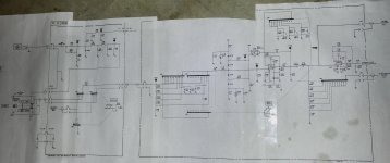
I attached a picture of the full A3 - A4 signal routing. I got tired of the 4 separate sheets of paper to trace the signal so I cut and taped them together to make my own fold-out.
I hooked up the scope and traced the input signal into the A4 and at A4 U100 TP 101 I have my input signal and it looks correct on the scope. Checking TP 103 on the output of U100 and I have a correct signal until I switch to the 100mV input range and then I have a flat line coming out of U100. I also notice a good bit of DC on the output of U100 and at 100mV range and below its pretty much on the neg rail at -14V with no sine wave, not even a clipped positive sine. The input of U100 (TP 101) has about -3V of DC on it at input ranges of 1V and below.
I began thinking that maybe the S4 switches came out of alignment or maybe one of the contacts was bad so I went through and verified that I have continuity on the S4 wafer contacts at the appropriate switch positions. I then decided to pull U100 and install a socket, I had a few LME49710's on hand so I tried one of those in place of the original 8451. Same problem, no output from U100.
My 339 is an Option 1 unit so it has two more input ranges.
Any idea's folks?
I attached a picture of the full A3 - A4 signal routing. I got tired of the 4 separate sheets of paper to trace the signal so I cut and taped them together to make my own fold-out.
Attachments
The is a dual gate mosfet before/at the first amplifier. It's purpose is to null the junction capacitance of the input protection diodes. Verify this circuit is working properly. You can do this by removing the mosfet or lifting one leg of the first protection diodes. If one of the coupling caps in the protection circuit is leaking it could cause this.
Okay I lifted one leg of CR102 & CR103 in the input protection string and retested and the problem still exists. I misspoke in my earlier post. The dc on the input to U100 drops to about -600mV on all ranges below 10V. However -14V (and no sine) is present at TP103 once the range selector is at the 100mV input range or lower.
After looking the schematics a bit more I realized why the DC measured at TP 101 would be highest at ranges below 10V. This being due to the signal being directly connected to the U100 input at those lower ranges with no voltage divider. C510 on the A3 should be blocking any DC from the input and I tried feeding a signal from my Amber 3501 into the 339 as well the other day with the same results, measuring DC and a loss of input signal at TP 103. I'll have to go back this evening and verify that I lifted the legs on the right diodes this morning. It doesn't seem likely that the DC on the input would come from much else.
I'm also beginning to wondering if I have some weird grounding issue. I'll inspect that also.
I'm also beginning to wondering if I have some weird grounding issue. I'll inspect that also.
- Home
- Design & Build
- Equipment & Tools
- HP339A distortion analyser