The 339A has been working good since the repair a few weeks ago so I decided to tweak on it a bit more. Although I had replaced U1 & U3 on the A1 osc. pcb I had not removed the zobel caps or compensation caps hanging off of these opamps. David had recommended this in the big 339A thread here post 1184. When I installed the new parts I had just lifted pin 8 as others had said would suffice.
Well there was a bit more performance than I had expected left in the 339A's oscillator with those parts removed. My measurement feeding the 339A's oscillator into the Amber 3501 analyzer before removing them was .0006% THD+N. Then after removing the capacitors C32, C48, C45, C46, C16, C17,C14, C15 removed and C49 changed to 0.1u polypropylene, per David's post. The measurement on my Amber 3501 dropped to .00045% about a 2.5dB reduction. The 339A's internal distortion analyzer showed a somewhat smaller reduction dropping from .00075% before to .00065% after removing those parts. I should mention these measurements were with the 400Hz HP and 30kHz LP filters active.
It seems the lesson here is that if you do install an LT1468 for U1 and a LME49710 for U3 in the oscillator then you should plan to remove the caps David listed in the thread above for max performance out of the oscillator. I've yet to replace U2 with a TL074 so there may be a bit more in it.
Last edited:
Hi KC,
Good stuff, I didn't realized that you were having an issue.
A heads up here, nice measuring. When you get the chance can you take
some pics? And post?
I also put your measurements in my HP339A summary blog (used to be wiki) but no one seems to be able to find anything in the wiki any longer. Hopefully people will find it
and it will help them out.
HP339A blog is here: BLOG LINK
Cheers,
When you get the chance can you take
some pics? And post?
Hello Sync,
Are you wanting a picture of the modded oscillator pcb?
I attached a pic of the 339A oscillator as measured on my Amber. I prefer to use the Amber 3501 analyzer as it has a -100dB range so I do not have to squint at the meter. What you cannot see is that the needle is wavering from about -.00066% to -.0007% on the Amber. This is approximately what I see on the HP 339A's analyzer as it wavers about +/- .00005% when measuring the same signal.
Attachments

Last edited:
Correction the last post should have read,
"What you cannot see is that the needle is wavering from about .00045% to .00047% on the Amber."
Not sure what I was thinking when I wrote that this morning. Maybe I should've finished my coffee first. 🙂
I had the numbers right in my post from a few days back.
Something I just noticed as well, the distortion performance of the 1.0 X 1kHz setting on the 339A oscillator improved substantially with the removal of these parts. Previously I had to use the 10 X 100Hz setting on the oscillator for best performance. The 1.0 X 1kHz setting had distortion of about .0012%, after the parts removal its now about .0008% so only slightly worse than the 10 X 100Hz setting which still has the better performance of the two.
Last edited:
Hi KC,
Yes, something of the board would be good I should think.
If it's handy, if not not big deal.
I think Richard had a pic and I know I posted one somewhere.
Hey, I don't know if those 3501 Amber are selling but over on the
bay they want $1K - $2K for them. Go figure.
I get a head ache looking at it, but then I bet the knobs are original
while in the HP they tend to break and be replaced a lot.
Cheers,
Hey, I don't know if those 3501 Amber are selling but over on the
bay they want $1K - $2K for them. Go figure.
I get a head ache looking at it, but then I bet the knobs are original
while in the HP they tend to break and be replaced a lot.
The 3501's you reference have been for sale on the bay for a Loooonnnng time and at those prices they will continue to be on there for a much longer time. The few that I have seen sell in an actual auction, not at a crazy high fixed price like the ones you mentioned, sold for approx $200. I paid $185 shipped for mine. It was a helluva bargain IMO for the measuring capability you get.
The 3501 takes a bit of getting used to especially if you're familiar with a different meter like the 339A, but once you get used to the layout it becomes quite intuitive. The knobs are more durable than the 339A however they are a clamping type of knob and do not use set screws so they'd be a pain to replace if ever needed. I really like the user configurable filters that Amber implemented and the fact that the footprint of the 3501 is about 70% the size of the 339A's.
I'll get you a fresh pic of the modded 339A oscillator pcb.
There is one 3501-a for $500 on eBay and a 5500 (questionable like the one I just got) for $350. If someone offers me $350 for my 3501 (w/ freq display etc. and ext power supply If I can find it) its available. I need the space.
Demian,
You can't be serious? You are in your new bench and you need space? Already?
How did that happen? You've got to post a pic please.
I recall your old bench with the slotted glass window...
gotta see the new improved larger bench.
Cheers,
You can't be serious? You are in your new bench and you need space? Already?
How did that happen? You've got to post a pic please.
I recall your old bench with the slotted glass window...
gotta see the new improved larger bench.
Cheers,
Sync-
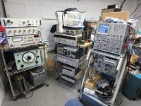
Here is the shop. Its stuffed and a mess. The workbench is dominated by the ST1200 test panel. I think I'll move that along soon since I'm not making much use of its real strengths in my work.
The workshop follows Boyles law- stuff expands to fill all available space. In the middle of this stuff are some large worktables piled high with projects and stuff that all need homes.
I attached the pictures as usual but DIYaudio seems to be misbehaving tonight. If they aren't working I'll repost once things are.
Attachments

@ Demian,
So clean, how can you stand it?
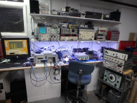
What is the thing sticking up in the 2nd pic from the left.
Red chair pic, on the main bent top between the power
supply and the head phones? Looks like some kind of
High Voltage Test Probe or something.
I can't tell from here though. I ask because I've got to build one
that won't screw up higher frequencies 40kHz to 1MHz,
and can withstand 40kV to 50kV. Affordability it key here.
Now I see why you like the under shelve lighting, just
looking at it, I like it.
While youre cleaning things out, if you have an old TEK SG603
I think and it's power supply let me know as I'm looking for one
that might be working.
My only criticism has nothing to do with you, but the cheezey
dual plastic wheels that the frame carts/shelves come with.
That is until I coated mine with a thin layer of Goop glue.
Now they roll over a grain of sand instead of getting stuck.
Thank you, you've grown into your larger space well!
Cheers,
So clean, how can you stand it?
What is the thing sticking up in the 2nd pic from the left.
Red chair pic, on the main bent top between the power
supply and the head phones? Looks like some kind of
High Voltage Test Probe or something.
I can't tell from here though. I ask because I've got to build one
that won't screw up higher frequencies 40kHz to 1MHz,
and can withstand 40kV to 50kV. Affordability it key here.
Now I see why you like the under shelve lighting, just
looking at it, I like it.
While youre cleaning things out, if you have an old TEK SG603
I think and it's power supply let me know as I'm looking for one
that might be working.
My only criticism has nothing to do with you, but the cheezey
dual plastic wheels that the frame carts/shelves come with.
That is until I coated mine with a thin layer of Goop glue.
Now they roll over a grain of sand instead of getting stuck.
Thank you, you've grown into your larger space well!
Cheers,
Sync-
This is quite off topic so i'll keep it brief. That object is an HP 1" measurement microphone with an NBS 9A headphone coupler. I use it as a primary reference for headphone sensitivity.
How are you generating 1 MHz at 40KV and staying in the same space?
The correct probe is a Tek P6015. The A version is the current one. Its $2000 and good for 40KV with a realistic derating curve. download the manual and study it. I don't know of an alternative that is practical. There are some solutions for 1 MegaVolt transmission lines etc. but none of those would be meaningful outside of a substation or high energy physics lab. There is also the Sensitive Research ESH electrostatic voltmeter that's good for 40KV in some models. I have one good for 30 KV from the surge testing (and an older P6015 and 2 P6013's).
Now back to getting the best from an HP339a (which I don't own).
Now back to getting the best from an HP339a (which I don't own).
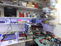
Demian, say it ain't so? I thought that was your 339A sitting there
just over the B&K Null.
So what am I doing? trying to work through various
automotive coils, measure their parasitic along with the
the actual spark, tested, documented what they put out,
under what conditions.
I guess I'll have to build one and hook it to the scope,
also I need the generator that has precise amplitude capability
for it.
Yeah, that is what the designer told me, that you'd only find this
stuff in an advanced physics lab...so you have to build it yourself.
Always good to check and see if someone has it.
I don't know if it is worthwhile to post in another thread or where.
I did a basline on the coils last year, with school in between not I have a
bit of time to build it and hopefully go to the next stage.
Then finally I need to build a measureing box to affix the coils
and define the parameters. Then measure the resultant spark energy.
Simple enough, right?
Cheers,
Careful Sync.
When I had my shop years ago a farmer brought in an electric fence gen. He begged me to test it for him. Needed to know if it worked. I still have the scope plugin with a burned out channel.
When I had my shop years ago a farmer brought in an electric fence gen. He begged me to test it for him. Needed to know if it worked. I still have the scope plugin with a burned out channel.
I thought there was some RF ion generator or some such involved. I would not even look at the voltage at the output. Use a suitable pickup coil and measure the current. Use a capacitive monitor for the voltage- a probe a few inches away to look at the waveform. A Pearson would be ideal but not easy to find. Wideband Current Monitors There are some on ebay but be sure of what you are looking at. They also make capacitive voltage dividers: Capacitive Voltage Dividers Pearson Electronics Model VD-305A Capacitive Voltage Divider | eBay ??
You can find anything on eBay.
Of course make sure your not chasing down a rabbit hole when what you want to know is somewhere else. I'm not sure how much correlation there is between spark energy and engine performance. Past a certain threshold it may not make a difference.
You can find anything on eBay.
Of course make sure your not chasing down a rabbit hole when what you want to know is somewhere else. I'm not sure how much correlation there is between spark energy and engine performance. Past a certain threshold it may not make a difference.
Hi Demian,
-Chris
You are correct. Once the fuel-air mixture is burning, a bigger spark won't make it burn any faster beyond a certain point. Motors under load would make use of a hotter spark, but once you have passed that threshold it doesn't make any difference.I'm not sure how much correlation there is between spark energy and engine performance. Past a certain threshold it may not make a difference.
-Chris
Yes, but using some DIYaudio parts among other things this is interesting
to me to build and it looks to be pretty good for testing as well.
Let me attach the four page information piece.
I've not done one but think I can and take some
measurements w/o killing myself.
The second pic is the spark shown on the Scope.
Cheers,
to me to build and it looks to be pretty good for testing as well.
Let me attach the four page information piece.
I've not done one but think I can and take some
measurements w/o killing myself.
The second pic is the spark shown on the Scope.
Cheers,
Attachments

Last edited:
Hi Sync,
Yes, but how does it feel between the two? Everyone knows that you can determine a lot more by your own sense than just by testing with instruments!
Yes, but how does it feel between the two? Everyone knows that you can determine a lot more by your own sense than just by testing with instruments!
This is down the road a piece, have to install the gas tank first,
then adjust the fuel pressure and get it running.
From there, I need to reassemble some of the gear I'll need on the bench
find another piece of gear or two, then start work on the ignition.
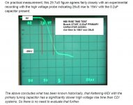
The original HEI by GM was based on the Motorola MC3334 IC and it used the MJ10012
TO-3 darlington transistors. The coil primary voltage peaks to about 450V just before the
coil unloads and initiates spark. But for the darlingtons, the C-E breadown voltage is about 400V. OOPS! They knew it caused problems so they specified using a 350V zener to clamp the output and keep from frying HEIs.
Then of course GM spec'd out the the HEI Module and had motorola make the die for them, they continued using the MJ10012 darlingtons and made millions of the units.
If GM would have used the MJ10014, or the MJ10024 they would have
eliminated countless mid RPM and high-RPM dropout and/or timing retarding
problem. Not to mention many of the HEI sufferred overheating issues with
low RPM running.
So from here, I'm trying to find some of the vintage ICs and Higher rated darlington
transistors to fab my own ignition boxes and be done with it. Most every after
market product now is Chinese and they tend to fail in use.
Chris, you are right, but if I told you or others here I could FEEL this, you'd
give me even more of a hard time.
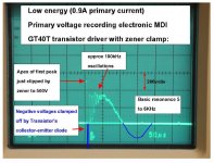
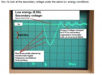
So I'll include HH's scope captures and state those
oscillations really affect the seat of the pants driving experience.
You expect the vehicle to really take off hard, but instead kind
of feel it burping farting around.
The California Air Resources Board (CARB) doesn't like for vehicles
to flatualate in any manner. I'm sure you Canucks noticed the affects,
as you are the "New Tropics".
then adjust the fuel pressure and get it running.
From there, I need to reassemble some of the gear I'll need on the bench
find another piece of gear or two, then start work on the ignition.
The original HEI by GM was based on the Motorola MC3334 IC and it used the MJ10012
TO-3 darlington transistors. The coil primary voltage peaks to about 450V just before the
coil unloads and initiates spark. But for the darlingtons, the C-E breadown voltage is about 400V. OOPS! They knew it caused problems so they specified using a 350V zener to clamp the output and keep from frying HEIs.
Then of course GM spec'd out the the HEI Module and had motorola make the die for them, they continued using the MJ10012 darlingtons and made millions of the units.
If GM would have used the MJ10014, or the MJ10024 they would have
eliminated countless mid RPM and high-RPM dropout and/or timing retarding
problem. Not to mention many of the HEI sufferred overheating issues with
low RPM running.
So from here, I'm trying to find some of the vintage ICs and Higher rated darlington
transistors to fab my own ignition boxes and be done with it. Most every after
market product now is Chinese and they tend to fail in use.
Chris, you are right, but if I told you or others here I could FEEL this, you'd
give me even more of a hard time.
So I'll include HH's scope captures and state those
oscillations really affect the seat of the pants driving experience.
You expect the vehicle to really take off hard, but instead kind
of feel it burping farting around.
The California Air Resources Board (CARB) doesn't like for vehicles
to flatualate in any manner. I'm sure you Canucks noticed the affects,
as you are the "New Tropics".
Attachments
Last edited:
- Home
- Design & Build
- Equipment & Tools
- HP339A distortion analyser