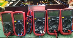
Ok @william2001 at least this is a starting point, now I have to borrow a DMM off some friend and go ahead with the P1 and P2, grazie @Zen Mod I will short the inputs with a common RCA-RCA signal cable while playing with P2 trying to get the closest to 0.
Questions if any of you is patient enough on a Sunday, it's already a big result for me to take measures which lead to a workaround but I am curious to know:
Grazie
Questions if any of you is patient enough on a Sunday, it's already a big result for me to take measures which lead to a workaround but I am curious to know:
- what the voltage swing on the mosfets is due to, is it due to the matching or what?
- what about the DC offset, what is that due to and how does it impact on the amp's performance?
Grazie
Giovanni,
Another suggestion is that after every adjustment of P1 / P2, you put the lid back on the chassis to help the amp reach thermal equilibrium. (The bias has a dependency on the temp so I suggest having the lid on except when making adjustmnets). Obviously this is easier if you can leave a probe clipped on a Source pin.
Good job with your bias measurements. I know this hasn't been easy but I am happy you are making progress. And the measurements have confirmed what many of us have suspected all along (based on your comment about the temperature) that the amp was not biased properly.
Cheers,
Dennis
Another suggestion is that after every adjustment of P1 / P2, you put the lid back on the chassis to help the amp reach thermal equilibrium. (The bias has a dependency on the temp so I suggest having the lid on except when making adjustmnets). Obviously this is easier if you can leave a probe clipped on a Source pin.
Good job with your bias measurements.
 I know this hasn't been easy but I am happy you are making progress. And the measurements have confirmed what many of us have suspected all along (based on your comment about the temperature) that the amp was not biased properly.
Cheers,
Dennis
Thank you very much @Dennis Hui I know that for all of you this is the ABC but for a total ignorant like me this is already an achievement, if I then make it work the way it is supposed to then even better, about time I clap myself 😉
Yep I know about allowing it to reach operating temperature with lid on, the thing applies to the BA-3 as a preamplifier too, I read about it as that's supposed to be the next step.
I hope I can find another DMM with a clip on probe so I can leave it clipped, with just two hands I think that's mandatory but I will try and get it there whatever the meter I can borrow.
Grazie
Yesterday after my last post here I asked a friend if today he could borrow me a DMM, half an hour before I know he would leave home I sent him another text, 5 minutes after he left home he texted me that he forgot "can we do it tomorrow?"
Can I start biasing and adjust DC offset with just one meter?
Can I start biasing and adjust DC offset with just one meter?
Sure. It's just a lot of back and forth with the meter leads as you "walk" P1 and P2 to their final destination. But sometimes you have to use what's available. A lot of probing increases the risk of an accidental slip, sparks, failed part, then certain disappointment.... be careful. That's why I like the "clip to it, and leave it alone" technique with the two meters.
better wait, just to ease it for your brain
while waiting for friend, order some inexpensive but cheap DMM, to have in future
Uni-T, for instance, are good even if cheap
while waiting for friend, order some inexpensive but cheap DMM, to have in future
Uni-T, for instance, are good even if cheap
Good morning from a finally sunny Capri!!!
Yep, temptation is to go ahead with the back and forth but, given my skills, I already consider myself lucky I didn't get electrocuted not fried anything inside the amp, I rather wait to tomorrow and in the meantime work out the position of P1 and P2, the boards are upside down and one of the two trimmers is so very close to a cap which makes it not too easy to reach with the screwdriver so today will be about finding out how to reach them.
By coincidence I was just looking at a meter on AliEx and hit these Uni-T of course I can't wait to get one so I will have to rely onto my friend's but I sure gonna get one, just wondering which one to pick.
Here pics of P1 and P2 and a view off the rear with the inputs already shorted
Thank you for the precious help and patience
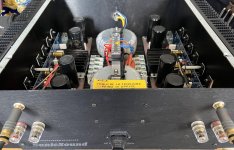
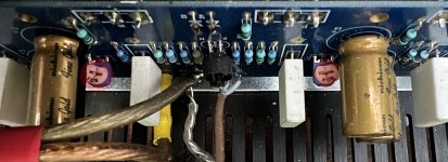
Yep, temptation is to go ahead with the back and forth but, given my skills, I already consider myself lucky I didn't get electrocuted not fried anything inside the amp, I rather wait to tomorrow and in the meantime work out the position of P1 and P2, the boards are upside down and one of the two trimmers is so very close to a cap which makes it not too easy to reach with the screwdriver so today will be about finding out how to reach them.
By coincidence I was just looking at a meter on AliEx and hit these Uni-T of course I can't wait to get one so I will have to rely onto my friend's but I sure gonna get one, just wondering which one to pick.
Here pics of P1 and P2 and a view off the rear with the inputs already shorted

Thank you for the precious help and patience


It's tricker doing it with one DMM so I suggest waiting.
It's also good to get a second meter for the future and I second ZM's suggestion of Uni-T. For the type of measurements we're doing, you don't need anything very fancy or expensive. (Heck, I have a DMM bought for a few dollars that is as good for trimming DC offset as my more expensive meters)
It's also good to get a second meter for the future and I second ZM's suggestion of Uni-T. For the type of measurements we're doing, you don't need anything very fancy or expensive. (Heck, I have a DMM bought for a few dollars that is as good for trimming DC offset as my more expensive meters)
It pains me to look at that picture of your amplifier that appears to still have the shorted turn issue on those toroids with the big bar across the top...
good eye, I missed to see that, still existing
shall we stop with any write-up, as long we don't see everything addressed ?

shall we stop with any write-up, as long we don't see everything addressed ?

Was the short turn brought up earlier? I have to admit to have missed it.
Maybe Giovanni can post more photos of the toroidal transformers and that bar to confirm that's an issue and how best to remediate.
Is there a list of issues for Giovanni to work through?
Maybe Giovanni can post more photos of the toroidal transformers and that bar to confirm that's an issue and how best to remediate.
Is there a list of issues for Giovanni to work through?
OK thanks. And there may also be a missing earth connection. 🙁
I can't really tell if it's a single metal bar or two unconnected segments.
I can't really tell if it's a single metal bar or two unconnected segments.
I believe it is a single bar across both transformers. It appears the bus bar is mounted to the top of it. Need a better angle.
Attaching a picture of how I got the amp and after being modded, for the sake of it the bar is continuous and there is continuity between it and the chassis, it and the negative speakers connectors...
The photos show the before and after the cure, please keep in account my English, the after is a local skilled tech who did the job after an issue with the missing soft start in the first iteration of the amp, he also moved the long connector on top for ease of maintenance I guess and because originally the cables were not fastened but welded (guessing what's the purpose of that connector if you then weld them).
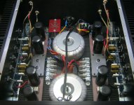
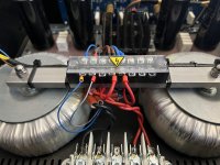
The photos show the before and after the cure, please keep in account my English, the after is a local skilled tech who did the job after an issue with the missing soft start in the first iteration of the amp, he also moved the long connector on top for ease of maintenance I guess and because originally the cables were not fastened but welded (guessing what's the purpose of that connector if you then weld them).


Giovanni, can you please post a photo of the power connector? In the Pictures thread I couldn't see if there is a chassis ground wire (and I do see one in the 'before' photo).
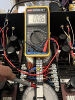
Also, what resistance value do you see between the negative speaker connector and the chassis? You said there's continuity, but I want to see if there is some reasonable resistance there indicating a ground lift.
Also, what resistance value do you see between the negative speaker connector and the chassis? You said there's continuity, but I want to see if there is some reasonable resistance there indicating a ground lift.
Here you go @Dennis Hui so far it seems there is no wire connected to the chassis but actually I can measure short between the transformers bar and the holes drilled onto the box, the resistance between negative speaker connector to transformers is as in the attached photo



- Home
- Amplifiers
- Pass Labs
- How to turn a dual mono F4 into a mono block?
