they can censor but the truth was exposed 🙂
So, are you going to respond to my post #71? 🙄
Mike
I said I bought the Q400 before they updated to Q401,
A400 Specifications
All specifications are subject to change.
General Spec
Sample Rates 192K, 48K
ADC and DAC Widths 24-bits
Input
Inputs 2 (Left + Right)
Type BNC Single Ended
Input DC Resistance to Ground 100K
Input AC Impedance 10K
Input Clip Level +3 dBV = 1.41 Vrms = 4Vpp
So of course it will clip at around 10 watts of sweep frequency test if not going through a divider.
Hey, you asked the questions, but I feel that the post was correct. The only company I will mention is Telefunken. They made good transistors amps at a certain time before the 1985, however I won't mention any other company, I don't want a ******* police people trying to sue me. This world is full of organized mafia and crooks, and the reason #1 is to make money, same time apply to amps.
I said I bought the Q400 before they updated to Q401,
A400 Specifications
All specifications are subject to change.
General Spec
Sample Rates 192K, 48K
ADC and DAC Widths 24-bits
Input
Inputs 2 (Left + Right)
Type BNC Single Ended
Input DC Resistance to Ground 100K
Input AC Impedance 10K
Input Clip Level +3 dBV = 1.41 Vrms = 4Vpp
So of course it will clip at around 10 watts of sweep frequency test if not going through a divider.
Hey, you asked the questions, but I feel that the post was correct. The only company I will mention is Telefunken. They made good transistors amps at a certain time before the 1985, however I won't mention any other company, I don't want a ******* police people trying to sue me. This world is full of organized mafia and crooks, and the reason #1 is to make money, same time apply to amps.
Well...As Carl Sagan said, extraordinary claims require extraordinary evidence, so without names and numbers your claims have no veracity.
If you aren't willing to back your claims up with actual evidence then we've reached a dead end.
And if you live somewhere that you really fear mentioning "any other company, I don't want a ******* police people trying to sue me. This world is full of organized mafia and crooks, and the reason #1 is to make money" maybe you should get out of there! 😱
Mike
they can censor but the truth was exposed 🙂
It is true, it is true!!!!!
They are all at it!
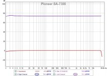
See the attached FR of another reputable 1980 hi-fi amplifier. Note the dastardly cunning raise of the bass response under 3Hz - and imagine how bad things could have been if they hadn't conspired with the soundcard maker (30 years later) to cover it up by sneaking in a low frequency roll-off of the card response. Shocking!
Now I know why this amp always tickled my toes - yes, I was quite simply tricked into buying it.
Hang them all out to dry, I say!
Attachments
I said I bought the Q400 before they updated to Q401,
A400 Specifications
All specifications are subject to change.
General Spec
Sample Rates 192K, 48K
ADC and DAC Widths 24-bits
Input
Inputs 2 (Left + Right)
Type BNC Single Ended
Input DC Resistance to Ground 100K
Input AC Impedance 10K
Input Clip Level +3 dBV = 1.41 Vrms = 4Vpp
So of course it will clip at around 10 watts of sweep frequency test if not going through a divider.
Hey, you asked the questions, but I feel that the post was correct. The only company I will mention is Telefunken. They made good transistors amps at a certain time before the 1985, however I won't mention any other company, I don't want a ******* police people trying to sue me. This world is full of organized mafia and crooks, and the reason #1 is to make money, same time apply to amps.
So, one last time...
Specifically:
What was the Exact test equipment used? (there's been some ambiguity on that)
How was the voltage divider utilized, where in the test circuit was it located and what R values were used?
What were the signal levels and waveform(s) used to feed the DUT?
What was the DUT's output connected to, dummy load or a speaker? (dummy load specs or speaker model name/number)
Were the DUT's stand alone power amps, integrated amps or receivers?
In the case where the DUTs were integrated amps or receivers, which inputs were used, was the loudness contour (if applicable) active or not, what was the volume control set for (attenuated or full gain).
If you want to have your claims accepted, you really need to disclose exactly what make/model the DUT's were, have no fear... I'm fairly confident that the thought police won't come and kick your door down if you disclose that info.
And finally, your math seems to be a little off...
...1.41 Vrms into a standard power amp with 26dB gain will provide 100W into an 8 ohm load, or 1.41 Vrms at the amp output would be about 1/4W into 8 ohms.Input Clip Level +3 dBV = 1.41 Vrms = 4Vpp
So of course it will clip at around 10 watts of sweep frequency test if not going through a divider.
Mike
Last edited:
Once i was repairing a Pioneer consumer vintage amplifier ...
Finished checked the usual but distortion analyzer showed far more THD than was originally written in specs .
Checked again decided to separate pre and main to find out where the distortion is coming from
Out of the blue the distortion of the main amplifier was exactly as much written on the service manual ...
Then noticed while checking with the service manual written exactly like that .
Total Harmonic Distortion ( amplifier only )
The number was there written for the amplifier only like one is going to use the amplifier alone ...integrated amplifier means that figures should be about the complete amplifier ..
Kind regards
Sakis
Once i was repairing a Pioneer consumer vintage amplifier ...
Finished checked the usual but distortion analyzer showed far more THD than was originally written in specs .
Checked again decided to separate pre and main to find out where the distortion is coming from
Out of the blue the distortion of the main amplifier was exactly as much written on the service manual ...
Then noticed while checking with the service manual written exactly like that .
Total Harmonic Distortion ( amplifier only )
The number was there written for the amplifier only like one is going to use the amplifier alone ...integrated amplifier means that figures should be about the complete amplifier ..
Kind regards
Sakis
So the power amp had better specs than the preamp section? Something doesn't seem right with that, I've never seen a case where the power amp had inherently better specs than the preamp. If the tone controls were in-circuit and even if set for the center/flat position, there's still the possibility that they aren't truly set flat due to potentiometer imperfections. Other than that I think there must have been something wrong with that preamp.
Mike
REVISOUND Resonance Vintage Sound - Stereo Amplifier / Receiver - Telefunken TRX 3000 - Telefunken TR 1200 - Telefunken TR500/550 - Telefunken TA 750
Pretty sure they all had a bass boost and high boost when tone controls set to "0"
I doubt my model was broken, I think it is a marketing trick no matter what you guys say
Pretty sure they all had a bass boost and high boost when tone controls set to "0"
I doubt my model was broken, I think it is a marketing trick no matter what you guys say
So the power amp had better specs than the preamp section? Something doesn't seem right with that, I've never seen a case where the power amp had inherently better specs than the preamp. If the tone controls were in-circuit and even if set for the center/flat position, there's still the possibility that they aren't truly set flat due to potentiometer imperfections. Other than that I think there must have been something wrong with that preamp.
Mike
You don't understand.
He said that the manual specified the THD% for the power section alone.
It is easy to deduct that the pre-amp contribute to distortion which the manufacturer didn't include in the amp spec. sheet.
"" due to potentiometer imperfection "" maybe, but I doubt this is an honest mistake
So, you still won't respond to my posts?
And about that "You don't understand" thing...yes I do. 😉
Mike
REVISOUND Resonance Vintage Sound - Stereo Amplifier / Receiver - Telefunken TRX 3000 - Telefunken TR 1200 - Telefunken TR500/550 - Telefunken TA 750
Pretty sure they all had a bass boost and high boost when tone controls set to "0"
I doubt my model was broken, I think it is a marketing trick no matter what you guys say
Hello, there is the explanation.....
On the picture of the 2 x 70W TR350 you can clearly see that the loudness switch is ON!
Elementary, Watson.
So the power amp had better specs than the preamp section? Something doesn't seem right with that, I've never seen a case where the power amp had inherently better specs than the preamp. If the tone controls were in-circuit and even if set for the center/flat position, there's still the possibility that they aren't truly set flat due to potentiometer imperfections. Other than that I think there must have been something wrong with that preamp.
Mike
probably my English is not good enough for that
The distortion figure was correct but corresponds only to the main amplifier.When the rest of the boards are connected ( preamplifier tone control and so on ) the distortion is bigger ...
meaning is that they print specs for distortion to present nice figures but THD in an integrated amplifier ( or other distortions ) should refer to the complete amplifier not the main amplifier only .
The trick is in the parenthesis (amplifier only )
Your English is good enough, I understood, Micheal is doing the hard bean.
Your English is good enough, I understood, Micheal is doing the hard bean.
That's weird ? you are from Canada aren't you? 😀😀😀😀😀
"" due to potentiometer imperfection "" maybe, but I doubt this is an honest mistake
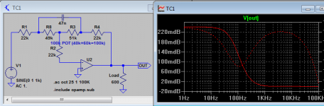
I have mentioned about difficulty in TC design (Remember Baxandall and you know the issue). So I will show you a common TC circuit for bass boost.
Most log pot is not logarithmic and most linear pot is not linear. If you put most pot's wiper in the center, the resistance is not 50% but less. Let's simulate this with LTspice. Assume the pot is 100k and in the center position the resistance distribution is 49k and 51k...
As you can see there is still bass boost.
Wait... I'm not sure which end is the minimum...
Attachments
Last edited:
I Need Sleep
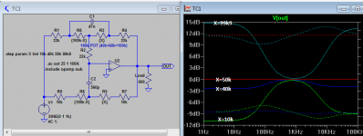
I had to check and measure a sample pot I have. Alps 50KAX2 (LOG POT). At left most position (-12dB bass attenuation) the center wiper is shorted to the left pin. At middle position (it is a 10 position pot) the left pin is 10K from the wiper. In this case (if log pot is used), the treble and bass are attenuated not boosted...
I checked a linear pot (B100K), which is rare so it is a cheap one...
The total resistance is 77k2. At center position it is 38k9, which is more than 50%...
Tried the other channel, total=80k, at center position it is 38k2, which is less than 50%... WTF!!!!
Attachments
- Status
- Not open for further replies.
- Home
- Member Areas
- The Lounge
- How to sell amplifiers (cheat the sound)