I would measure the individual drivers 0.5 to 1m distance.
Directly Infront and off to the side.
Then from the listening chair, assuming you can move them around a bit, back and forth etc, and perhaps play with X/O points and slopes.
I measure my driver's / horns individually when I've just made / created them.
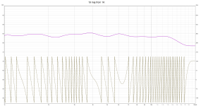
Test sweeps etc, calibrated measuring mic
To see how they perform vs Hornresp🙂
Generally pretty good.
After that in room at the listening spot for tweaks.
As much as it's nice to chase flat response using DSP, it just tends to suck the life out of the music.
Much prefer with a few essential a room mode corrections as possible on bass only.
Over the years I've tweaked the system more by listening to music that stimulates certain aspects and comparing with my norms, as my measuring.
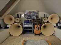
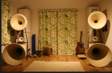
Pic of system incarnations, measure / listen to.
Directly Infront and off to the side.
Then from the listening chair, assuming you can move them around a bit, back and forth etc, and perhaps play with X/O points and slopes.
I measure my driver's / horns individually when I've just made / created them.
Test sweeps etc, calibrated measuring mic
To see how they perform vs Hornresp🙂
Generally pretty good.
After that in room at the listening spot for tweaks.
As much as it's nice to chase flat response using DSP, it just tends to suck the life out of the music.
Much prefer with a few essential a room mode corrections as possible on bass only.
Over the years I've tweaked the system more by listening to music that stimulates certain aspects and comparing with my norms, as my measuring.
Pic of system incarnations, measure / listen to.
Attachments
I assume he was under some sort of budget so he made a vise compromise with the inductors.
Dont think so, the upgrade cost 75% as much as the orginal VR-4 speakers, and was 2.500 usd$ in 2001 plus shipping.
And Albert shoulden´t have use the words "Nothing has been overlooked, no compromises have been made; we are in search of perfection!" if he thought there was something to be gained with coils witout iron.
And Albert whrite:
Crossovers, Circuit Design and Parts:
As with the original VR-4 system, the new VR-5 modification utilizes two crossover boards to allow bi-amping and/or bi-wiring. The woofer crossover board is installed in the woofer module and uses three 1,500 watt inductors (one air core and two steel laminate-cored units with 16AWG wire), four capacitors, and one high power resistor. The slope is acoustic fourth order and is corrected for both transient response and phase response, using the driver parameters as the target alignment for a 200Hz crossover point.
A Zobel conjugate circuit is employed to correct for impedance variation caused by the vent tuning and the woofer's impedance curve. Since the overall system impedance has a very flat measurement after correction.
Regards John
Attachments
I would measure the individual drivers 0.5 to 1m distance.
Directly Infront and off to the side.
Then from the listening chair, assuming you can move them around a bit, back and forth etc, and perhaps play with X/O points and slopes.
I measure my driver's / horns individually when I've just made / created them.
Test sweeps etc, calibrated measuring mic
To see how they perform vs Hornresp🙂
Generally pretty good.
After that in room at the listening spot for tweaks.
As much as it's nice to chase flat response using DSP, it just tends to suck the life out of the music.
Much prefer with a few essential a room mode corrections as possible on bass only.
Over the years I've tweaked the system more by listening to music that stimulates certain aspects and comparing with my norms, as my measuring.
Pic of system incarnations, measure / listen to.
WoW!....That was a horn-build 😀
Have a calibrated mic, and makes the measurements in the actual room.
Im not either a "DSP-guy" 👍
But haven´t use Hornresp, and are at the time "full in my head" with all other "new" learning of programs hahaha.
This is the Aga and jbl 2405h from 1K.
And seems as i could make with splcurve i want with these drivers!.
Regards John