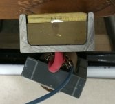
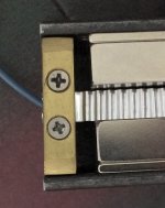
The connections have to be very good. Heavy copper or brass, and surfaces very flat. I used cover part of 1/4 inch thick stock. Screws should be as close to ribbon as possible and tighten carefully so same pressure on each side. Also put a VERY thin coat of silicone oil on the part that goes under it. No more corrosion. Wires for smaller length ribbons have to be large, around # 8. And a good transformer is a must.
Attachments
Don't have any trouble with my connections using aluminium tape and zinc plated steel washers and 5 mm bolts and nuts , lasted for over 20 years no problem!
Current for short ribbons can be large 30 to 100 amps since it is only like .02 to .03 ohms. Resistance of small wire can be more than the ribbon. That is why the transformer I made uses heavy sheet copper and wires are very short. Keeps loss at a minimum.
Jonas, I used Circuitwork silver ink to repair my Apogee's main panel with some 15 years ago and it is still stiking and conducting to this day !! 😉
I my ESL's I used MG's Nickel Print as it was much cheaper and Nickle doesn't oxidize either.
FWIW
jer 🙂
I my ESL's I used MG's Nickel Print as it was much cheaper and Nickle doesn't oxidize either.
FWIW
jer 🙂
I submerged the contact points of alu membrane in oil and brushed them with a low abrasive nylon brush, then applied a thin layer of vaseline, problems gone!
A Member posted a video of assembling a pole mounted mains transformer.
Very interesting.
Two significant observations.
a.) The LV secondary winding is wound using aluminium foil onto the core. Few turns but lots of area. A strip of copper foil could be used.
b.) The HV primary winding is wound around the secondary using copper wire. Lot's of turns using adequate cross-sectional area for the rated primary current.
This seemed a clever way to get the few secondary turns, that would be much more expensive using multi-paralleled copper wire.
And directly applicable to a speaker transformer.
http://www.diyaudio.com/forums/planars-exotics/185592-criterion-85-es-2.html#post2516875 Balun or cable transformers as rightly mentioned in previous post would be the best.
All you need is single turn: wire through the center of toroids with the primary already woundhttp://www.diyaudio.com/forums/plan...trostatic-headphone-driver-7.html#post3372969 foil will complete the single turn secondary.
I would though check for stray field from the magnetic system which could saturate x-former's core if the latter is too close to magnets.
http://www.magnetec.de/fileadmin/pdf/data-sheets/m-452.pdf
MAGNETEC GmbH: LM Cores
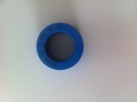
Bought two magnetec cores. they are iron powder in a plastic case.the iron can be heard if the box shaken.Having trouble finding the right data, to the number of winding an approximately 0.4 ohm => 8 ohm crossover 300-500 hz.
MAGNETEC GmbH: LM Cores
Bought two magnetec cores. they are iron powder in a plastic case.the iron can be heard if the box shaken.Having trouble finding the right data, to the number of winding an approximately 0.4 ohm => 8 ohm crossover 300-500 hz.
Attachments
http://www.magnetec.de/fileadmin/pdf/data-sheets/m-452.pdf
MAGNETEC GmbH: LM Cores
Bought two magnetec cores. they are iron powder in a plastic case.the iron can be heard if the box shaken.Having trouble finding the right data, to the number of winding an approximately 0.4 ohm => 8 ohm crossover 300-500 hz.
Let's see. What you've got is tape wound cores.
If you stack two cores you've got, then
having Fcross=300 Hz it yeilds 11 primary turns. I would not apply more than 4.5 Vrms to the primary.
On the other hand since you want sqrt 8/0.4=4.47 it yeilds 2.5 turns secondary, which is not doable. Then there are two ways.
First round 2.5 to 3 which means 3 turn secondary and 13(14) primary. That would work @ 300 Hz or you could round secondary down to 2 which means 9 turns primary, but the min X-former operating frequency would be 22% higher.
Finally the assumption I've used to calculate was equality of the x-former primary inductive impedance to the one to match i.e. 8 Ohm.
Sure it's the very minimum number of turns you need. So feel free to increase number of turns, keeping transformation ratio (4.47).
I do not know what is the power level you need to transfer to the ribbon.
Knowing that I could tell more.
On the other hand having magnetizing current equal to the load one, even @ crossover frequency is probably not wise.
Anyways I would keep primary (and secondary as well) @ single layer i.e. approx 40 turns primary @ 1 mm magnet wire. The latter would work up to 15 Vrms and about 2 Amp thus giving you 32 W of apparent power, again @ 300 Hz.
EDIT
Almost forgot: Do not wind too tight. If you apply mechanical stress to the core itself i.e. warping the container you will kill the core. It is not wise to rattle the core as well. Rattling is kinda weird core is usually fixed inside the by a bits of soft silicone or foam.
Last edited:
Ok Thanks
One core are too small for 300hz ,will one then work at 500 hz.
The ribbon will be 25 mm 0.004mm 1,8 meter long. N35 neo magnets maybe 92-94 db ?.
The turns ratio will be the same ?.
The rattle is low 🙂
Thanks again
One core are too small for 300hz ,will one then work at 500 hz.
The ribbon will be 25 mm 0.004mm 1,8 meter long. N35 neo magnets maybe 92-94 db ?.
The turns ratio will be the same ?.
The rattle is low 🙂
Thanks again
Look, I do not know how much power you were planning for the ribbon? 5...10....50 watts
???
Neither I know the sensitivity i.e. dB per W (sound pressure you stated in dB).
Otherwise the core will saturate before you reach the sound pressure level you expected
And yes one core will be fine at 2 times lower voltage i.e. 4 times lower apparent power for the same number of turns and wire dia
Last edited:
I do not play loud so. A 94 db ribbon will be 109db at 32 watt.
So 32watt will probably be enough. If i is not I can crossover higher or
i will buy bigger cores. The first ting is to test there sound impact.
So 32watt will probably be enough. If i is not I can crossover higher or
i will buy bigger cores. The first ting is to test there sound impact.
Hmmm, 0.4 ohms.. can you add a picture of the ribbon speaker?
Do the "Try-it-out" method, start with two sec-windings of copper foil and 20-30 prim-windings of enameled ordinary 0.8-1 mm wire ....I know that this will give over 40 ohms theoretically, but try it anyway. Theory and reality seldom walk hand in hand when it comes to audio transformers .....
And most importantly, can you please tell us where you found the 0.004m alu?
Last edited:
Poor me,
it's 94 dB/Wm.
I would of used flat strand of 5 1mm wires instead of foil. Spread secondary evenly over the core. Good luck.
it's 94 dB/Wm.
I would of used flat strand of 5 1mm wires instead of foil. Spread secondary evenly over the core. Good luck.
.....................
The ribbon will be 25 mm 0.004mm 1,8 meter long. N35 neo magnets maybe 92-94 db.................
That's quite a thick/thin foil depending on who you read!.......................And most importantly, can you please tell us where you found the 0.004m alu?
What is the current capacity of 0.16thou/mil foil !
Or try to drive the ribbon without transformer, just put 40 parallel wired 0.5watt 100 ohm metal film resistors in series with the ribbon...
What puzzles me is "A good transformer"
Even using rather wide connections for the driver, for instance 2 cm wide foil, one will get approximately 1 micro Henry of inductance per meter of length. 4 cm wide will help a bit: 0.86 uH. That goes for 50 cm long driver with termination leads of the same length, given that there is no coupling between termination and strip itself.
With 1mm thick primary and foil strip secondary of 4 turns stray inductance would be at least one order of magnitude less than that. Even with that inductance associated electrical roll off frequency would be around 60 kHz.
Surely, artificial increase of distances between pri and sec etc. would not help the cause.
It seems though any reasonably accurate X-former design will suffice.
This leaves us with the simple considerations to use: high saturation flux density, narrow hysteresis, high and preferably linear permeability for the core, and possibly low losses.
Ferrite does not satisfy Bs, coercive force and linearity... I would rather not use cut cores of nano/amorph material. Unevenness and irregular shorts in a gap do create all kind of effects.
In regard to powder cores: please be aware that Bs is much lower of that of the original material, permeability is low as well.
The last but not the least, please be aware of possible saturation problems with non gapped design due to DC offset voltage (amplifier's one) at the primary.
I can not display images. I have not built anything yet. and aluminum foil, I have from a now closed capacitor manufacturer.
Alexberg will the powder it self not act as a spread out gab, this gives the lower permeability.And even though these cores are not perfect. Isn´t the data better than ferrit ?
Alexberg will the powder it self not act as a spread out gab, this gives the lower permeability.And even though these cores are not perfect. Isn´t the data better than ferrit ?
- Status
- Not open for further replies.
- Home
- Loudspeakers
- Planars & Exotics
- How to make a good transformer for ribbon tweeter?