Each board gets its own input return/ground. follow layout post #91.
http://www.diyaudio.com/forums/chip-amps/303212-how-get-rid-interferences-tda7293-10.html#post4992330
You need to install the resistor on each board.
http://www.diyaudio.com/forums/chip-amps/303212-how-get-rid-interferences-tda7293-10.html#post4992330
You need to install the resistor on each board.
Last edited:
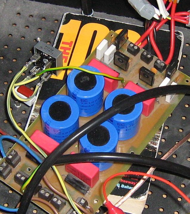
If u are using this board then u have big groud loop.I did solder them onto the small connectors, so I can try things. Disadvantage is I guess, a little bit of the shield missing. Found a 2.2 ohm resistor, soldered it in. Removed that black connector to make room and get rid of an antenna. Hope I find some time to try it tonight.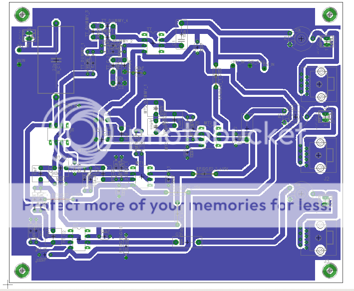
The filter: essentially ground plane and each opamp gets 100nF caps in the rail
I think I make 2 grounds, one for shield and one for signal. Have to make it 24 dB instead 12 dB anyawy. Found some RCA jumpers, this and shielded RCA sockets might be a nice idea.
Got some Nylon standoffs from ebay, no idea if that would help. After all its magnetic and capacitive coupling, nothing I can do. And the standoffs are not touching copper on the PCBs.
By the way, thank you for all that effort!
I will put the resistor on 3 boards and conect it to the xover. See what happens then. I just put it on one board first so I can compare the differences.
For now can slice open that loop at the top of the xover board, the next one will be way smaller, guess 2 layer
For now can slice open that loop at the top of the xover board, the next one will be way smaller, guess 2 layer
Last edited:

the PSU for the crossover, the transformers ground is not connected to the chassis. Its 1/2W or so. The crossover is grounded via the shield. This Is the most complicated bit, as it connects between the outside world and the amps.
enter: veroboard.
enter: veroboard.
Last edited by a moderator:
Here is some more info on GLB.http://www.diyaudio.com/forums/chip-amps/265827-lm3886-fullrange-10.html#post4295969
1000V for the capacitor? Ok. Guess its to be sure.
Does the crossover power supply need one as well?
Does the crossover power supply need one as well?
ok,thats done. Seems to be a bit quieter now, even when I interconnect inputs of 2 amps. I left one amp without that 2.2 ohm resistor, that one gets quieter. The other one with the resistor is already quiet.
found this:
Earthing (Grounding) Your Hi-Fi - Tricks and Techniques

ok, put the transformer back into the chassis. Even with the wiring as it is now, as long I use video cable to interconect the amps, its quiet.Audio cable does not help. The interesting thing, when I switch the transformer off, so it drains the PSU capacitors, the buzz gets louder
The chipamp might be going into oscillation as the supply rails droop.
Many amplifiers with compromised compensation do this during start up and shut down.
A speaker isolating relay hides the problem. If this is what is happening the short duration of the oscillation usually does not kill the amplifier.
Many amplifiers with compromised compensation do this during start up and shut down.
A speaker isolating relay hides the problem. If this is what is happening the short duration of the oscillation usually does not kill the amplifier.
there is a mute input on the TDAs, so I can first swtich on the PSUand some later the chip. Switching off in reverse.
It may be as well, since when the toroid is swiche off, it does not supply a centre tap voltage and then the PSU ground is 10 ohm away from chassis ground
It may be as well, since when the toroid is swiche off, it does not supply a centre tap voltage and then the PSU ground is 10 ohm away from chassis ground
Are you switching off the PSU? Or are you unplugging it? If you are unplugging it, you are also disconnecting PE. Earlier tests showed that the amp hums more when the chassis/amp is not connected to PE.
switching off the PSU. So then the centre tap reference of the toroid disappears. Then its PSU ground to GLB to chassis to safety earth.
Here some fun snaps
1st is current from PSU to amp, 2nd is current from toroid to PSU. Ground noise does not show up in the own noise of the ebay gadget
cannot use flash light, so its a bit blurred
Here some fun snaps
1st is current from PSU to amp, 2nd is current from toroid to PSU. Ground noise does not show up in the own noise of the ebay gadget
cannot use flash light, so its a bit blurred
Last edited:
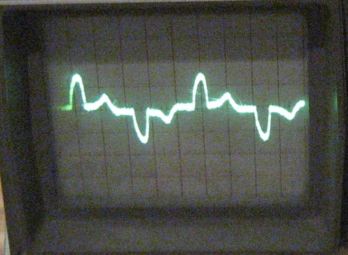
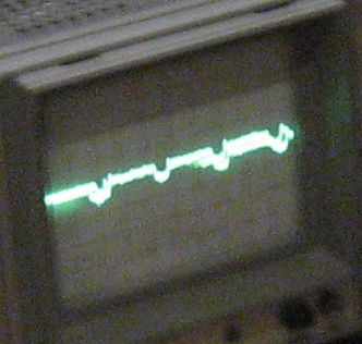
and thats the primary winding currents. Maybe I overlay the voltage in some stage, just because I can. At least now its clear, why there is no clean 50Hz hum, but lots of overtones, this will be 100Hz and more multiples. I think there were some small sqare wave currents on the centre tap of the toroid secondary.
So over the next days I will clean the wiring up and put in the active crossover, that should not make much difference.
Last edited:
Not a problem as long as you don't run these cables alongside the input cables.
Try measuring the output with the input shorted. Also, post the unit/div as it has very little meaning without it.
Try measuring the output with the input shorted. Also, post the unit/div as it has very little meaning without it.
this is just in the power supply lines and its pretty hard to gauge. I think its normal. Put it in for the future reader. This is your current shapes, no neat sinewaves and thats why it causes buzz rather neat hum.
Its a cheap current to BNC clamp meter and it did not show anything on the outputs/speaker cables and on the ground lines to the TDA boards. It has 20kHz sampling rate and 1mV per 10mA, its own noise then was more than the lines I tested. A la ground and outputs/speaker. Even with the buzz, when the toroid is cut off AC and the PCU capacitors discharge.
The ground from PSU to GLB and GLB to chassis did not show anything either, just digitizing noise. I will chase up some voltage screenshot from the speaker output later. Looked like some 50Hz sawtooth wit some small spikes and on the lines of 20mV. And some white noise. Its pretty much at the limit of the scope
Last edited:
That square wave why we put ceramic caps across the post transformer rectifier, to get rid of them. As I mentioned in a post long, long ago. The fourier transform of a square wave includes high frequency components, and high frequencies transmit well to high gain circuits because they are radio frequencies. So you get a rasping noise at 50 or 100 hz incidence.At least now its clear, why there is no clean 50Hz hum, but lots of overtones, this will be 100Hz and more multiples. I think there were some small sqare wave currents on the centre tap of the toroid secondary.
Ceramic caps are low inductance so they have low resistance to RF. Impedance is proportional to frequency times inductance. Wound caps have higher inductance because the windings make the current go in circles, so the RF won't short out through them.
There are new cheap stacked film caps available because of the prevalence of switcher power supplies running at midium frequencies. I'm starting to experiment with stacked film caps I salvaged out of dead CFL bulbs. Imagine a 0.2 uf 400 v stacked film cap that costs nothing across the rectifier! Possibly a lot better at sharp edge supression than those 0.01 uf 1000 v ceramic caps amp builders used to use across the rectifier.
I've had to pay $.77 each for 0.1 uf 500 v caps I intended for this location, and since the voltage rating comes from a ****ese factory, there is some question as to whether they will stand refrigerator motor shutoff transients whanging through the power cord and the power transformer. A CFL bulb salvage capacitor rated "K" saw those motor transients all day & withstood them.
Last edited:
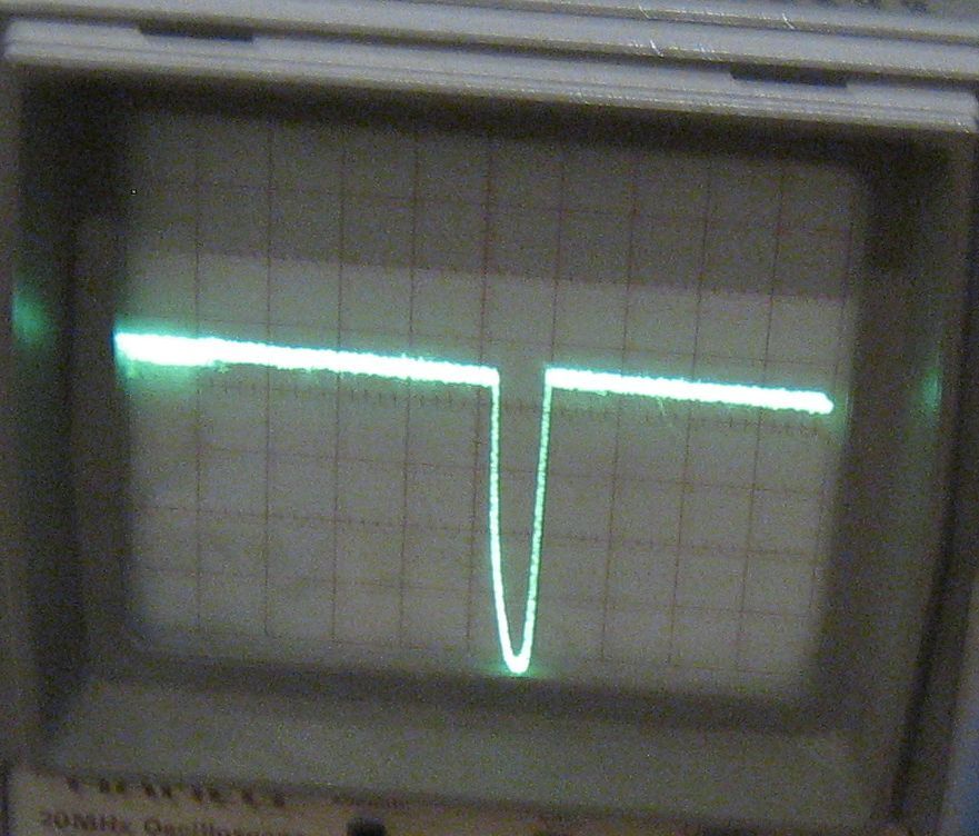
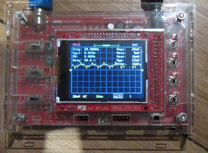
there is something on RC snubbers on rectifiers, you can use some small resistor in series with the capacitor.Or use a ceramic one, because it has higher ESR and the value does not matter that much. I will post some layout soon. These graphs, Its 500mA when the PSU capacitors are charging (2nd image), 3rd image is 80mA in the toroid primary.
Could not see any small ripple and from testing in some earlier posts the PSU is clean, no noise created from that.
image: current clamp to ebay digital osci kit, 1mV is 10mA, so thats 160mA across or 80mA half wave. At 50 Hz.
Have to work out, how to calibrate that offset, as it should move around 0.
Can make anather image tonight, I think it was 50mV cor the PSU charging current or 500mA then. Still, no ripple.
Last edited:
The small current peaks at 0V crossover are the transformer's magnetising current. The larger current peaks are because the load current only flows when the voltage of the secondary is higher than the (DC) voltage of the load.
- Home
- Amplifiers
- Chip Amps
- how to get rid of interferences-TDA7293