essentially everything goes onto one star ground at once? Signal and power?
I still should try Marks picture further up, use cheap RCA cable first and then coax.
That is the best way to start, yes, and speaker return. Take it one step at a time. Check all your polarities, I mean inputs and outputs mainly. Anything else and you would already know about it!! Cheap RCA is fine, coax, if you mean like aerial cable, is not necessary
Last edited:
No, connecting the speaker return to anywhere but the feedback return will increase THD and do little in reducing hum. We want the best audio possible then worry about hum.
Coax input cable should run from source to the amp board,
Connect the PSU ground to chassis.
Coax input cable should run from source to the amp board,
Connect the PSU ground to chassis.
Ok. I don't want to add to the confusion. I thought what I was describing was standard practice.
Take the speaker return back to star ground, not pcb................. Try connecting signal return to the chassis
Separating any two wire signal connection into one half going to the Receiver and the other half going to some remote tap is WRONG.I thought what I was describing was standard practice.
The two wires MUST be close coupled along the whole route (including the terminations) from Source to Receiver.
There are many on this Forum who break this two wire connection all the time and can't see why it is wrong.
Last edited:
Thanks Andrew. I'm not helping here I'll butt out. Shouldn't the chassis be at signal ground potential? I understand the close coupling....I think! I didn't mean to break close coupling of signal input, just tie to chassis as well. How about speaker return, Mark is right I guess?
Last edited:
Many years ago I used the same arrangement as I do now, But I described it differently.
I kept referring to taking voltage references to remote audio grounds.
I began to realise that it was confusing and tried to find a new description that avoided the ambiguity whenever the "ground" word was used. It's the word that causes the confusion.
Then I adopted the close coupled two wire connection as the MAIN unambiguous description.
Too many still think and use the ground word. I can't stop the billions that misuse that word.
I fear I am on a hiding to nothing, but I'll keep trying.
Unfortunately it's worse in North America: They use "ground" where we mean "Earth", the short form of Protective Earth.
Last edited:
I've seen the term quiet ground used quite a bit, seems helpful. Also terms receiver and transmitter are unambiguous
I did not want to connect the chassis to anything just yet as it may start radiating, more variables. Will try cables tonight. Coax, found these cheap RCA video cables, its an antenna cable, just thinner and more flexible. And the wire core is a bit thicker, easier to solder. When this is done, I will try to assemble the amps again.Dont want to change the rest of the setup just yet, will introduce new variables. But for now it seems its not the grounding and not the PSU, bets are on interferences
Two things we know. Earth (PE) connects to chassis and amp/PSU ground connects to chassis. These are minimal safety requirements. So lets start from there. We can then look at modifying the amp boards and grounding.
Ground as used by TI, ST, AES and everyone else but NASA and AndrewT.
Ground as used by TI, ST, AES and everyone else but NASA and AndrewT.
and alas, connecting PE to the chassis makes it quieter. Used alligator from scope to a screw in the chassis. Taking it off, louder. Putting it back, you hear that arcing noise.
Connected inputs of two amps with
A) twisted cable. Same noise if looping (signal) ground trough or not
B) chopped up cheap RCA cable, screen only connected to one amp signal ground.
C)chopped up cheap video RCA cable, essentially solid core coax half as thin as antenna cable, more shield than B), but still no foil, just wire.
B and C somewhat quieter than A, I think even better results, when chassis is grounded to scope ground. PSU still grounded to 3 prong plug via alligator clips. Different power points, but same room and room is connected as star.
In VIC/Oz you still need a licensed electrician to put a light bulb in. So hope I don't get slapped by the long arm of the electricians guilde, formed in 73BC.
Am a bit reluctant to connect the 3 prong plug to the chassis, as this has the live as well and will introduce more hum. Back tomorrow.
edit: seems the grond off the scope is somewhat better than that of the plug for the transformer. Even though the scope is on another power point and then there is a 5m extension lead back
Last edited:
tried something this morning, antenna cable with shield 100ohm and 100pF to ground on one of the amp PCBs is quieter again. The chassis ground is not connected to anything. Speaker gnd is at amps, then to PSU then to cable feeding the toroid. Still, just grounding the housing makes things quieter. Like this. Shield only connected to one amp board, signal goes through.
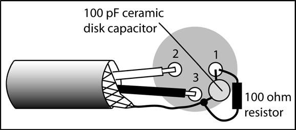
it seems to be quieter than put the shield straight onto ground
I remember reading something similar for unbalanced, instead putting the shield trough, use a capacitor and resistor.
I remember reading something similar for unbalanced, instead putting the shield trough, use a capacitor and resistor.
Last edited:
You are applying a solution that is used for balanced circuits. Pin1 is only shield. Your amp uses unbalanced circuits where the shield is part of the signal. Lets trace the signal path. It starts at the source, runs along the centre core of the coaxial cable to the amp board, through R1 and returns to the source along the shield of the coaxial cable.
The solution is to insert a 1 ohm resister in the ground loop where it will reduce the current flow that causes the hum but has the least impact on the input signal.
The solution is to insert a 1 ohm resister in the ground loop where it will reduce the current flow that causes the hum but has the least impact on the input signal.
Attachments
Last edited:
I was thinking, signal return should be separated from shield ground. Thats why the 2 poled cable with shield. But if its just as signal reference, as all the grounds will meet at the chassis ground. And the sgnal current is very small, so its return could be via shield or power ground, as their cable cross sections are way higer. Page 21 of the pdf I linked has the unbalanced option, seems their signal reference is at the PSU ground. This better gets to the chassis ground. I guess metal chassis gets current induced from ambient, and inuces that to internal wiring. When I come close to the audio wires without touching them, there is a hum.
Read some on shielding, maybe I can find reallu short RCA cables, makes life easier. Don't want to solder them onto the boards, makes testing harder.
Your image, good old Eagle, will Autodesk kill it, same as Ecotect? Will get the 1 ohm resistor on Friday, more reason to look forward to the weekend.
Last edited:
Step 4 will insert a Ground Loop Breaker between PSU and Chassis. I will post the layout before Friday so that you can get those parts too.
Check DC at the output after installing the resistors and before connecting the load.
You would not be the first to try something different than coaxial or twisted pair as input wiring. Things like using a separate coaxial for the return, it never works. Try soldering the coaxial cables on to the small connectors you are using.
I have all the schematics except the one for the crossover. Please post it. You will probably need to mod that board too.
Last edited:
The filter: essentially ground plane and each opamp gets 100nF caps in the rail
I think I make 2 grounds, one for shield and one for signal. Have to make it 24 dB instead 12 dB anyawy. Found some RCA jumpers, this and shielded RCA sockets might be a nice idea.
Got some Nylon standoffs from ebay, no idea if that would help. After all its magnetic and capacitive coupling, nothing I can do. And the standoffs are not touching copper on the PCBs.
By the way, thank you for all that effort!
Last edited:
The secret is loop area. Route the return alongside/underneath the supply. There are plenty of good PCB examples to be found on diyAudio.
seems to work with the 2.2 ohm. I just did one board and does now matter, which board gets the shield onto the ground, the one with the resistor is quiet. As in, the RCA cable I interconnected the boards with has the shield just on one pin.
- Home
- Amplifiers
- Chip Amps
- how to get rid of interferences-TDA7293