So, how much voltage does the 01A provide, am I correct that it would be 16v since it has a mu of 8 and the source is 2v?Thanks for the post. To be clear - the 01A is working fine at lower voltages into the EL12n, since I don't listen loud. A more sensitive output tube isn't necessary. A mu of 15-20 is enough for my system and I know of no power tubes of minimum 18W dissipation that have a higher mu in triode.
So what I'm doing is researching performance at higher volumes where slew rate may come into it. Now, to be frank I know very little of slew rate. Also it was my understanding that more current was needed to cope with the input capacitance of the output tube.
Are you saying that, from a voltage standpoint, the EL12N is actually being driven to full power but that the power is somehow unusable due to issues with slew rate (whatever that is) and the input capacitance of the EL12N?
I'd like to have a better understanding of the factors that seem be limiting the amp's ability to play louder. I may want to try the 01A sometime or the 26, which has a similar mu and I don't want to run into the same problem.
I can't help you here, because I don't fully understand this myself. The power isn't "unusable" - the sound is good. I'm just trying to understand what happens at higher volumes myself. I'd say the sound was better at lower volumes, but there's not too much difference. I'm wondering if there is some kind of overload but I don't know even if that's the case, or where it might be coming from. The idea of a cathode follower was to see if the sound is more effortless at higher volumes. The EL12n isn't too difficult to drive.
The EL12n may not be "difficult to drive" but that doesn't necessarily mean that the 01A has sufficient voltage to drive it. I'm unfamiliar with it and the only data sheet I've seen is in German.I can't help you here, because I don't fully understand this myself. The power isn't "unusable" - the sound is good. I'm just trying to understand what happens at higher volumes myself. I'd say the sound was better at lower volumes, but there's not too much difference. I'm wondering if there is some kind of overload but I don't know even if that's the case, or where it might be coming from. The idea of a cathode follower was to see if the sound is more effortless at higher volumes. The EL12n isn't too difficult to drive.
It could be that drive voltage is not the issue but wouldn't you want to know for sure so you can rule that out, as a first step.
Perhaps someone can comment on the drive requirements of the EL12N?? Don't you need to draw a load line to determine that?
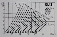
The EL12 typical operating point is 250V, 72mA, -7V, so making 14Vpp grid swing is not difficult.
But it's also true, that 01a HF behaviour even at 20kHz far behind from any beefy driver.
But it's also true, that 01a HF behaviour even at 20kHz far behind from any beefy driver.
The EL12n may not be "difficult to drive" but that doesn't necessarily mean that the 01A has sufficient voltage to drive it.
Overall gain is system dependent in terms of whether it's enough for your speakers, room, volume level etc. In my case voltage gain is absolutely not the issue - I have enough gain. I use Alpair 10M single units. For others they might want more gain but that's not my issue.
Operating point is around 264v, 70mA, -9.5v
Last edited:

Oh yes, in triode it's more linear.
Are you measure THD at different swings?
No - I will have to look up the formula! What do you think?
Hi Bela. The EL12n is in triode - you are aware of this?
What's the power output of these in triode?
Looking at the schematic in the opening post, you appear to be running the 01a at the maximum voltage. Have you tried lowering the voltage and increasing the current. Looking at the schematic 4ma 110v -4.5v, might be a better operating point. The plate imedance curve has started to level off at this point. Also the slew rate should be improved due to the increased current.
What I don't understand is how the current limit is determined and whether the cathode would be able to supply and sustain the current. I think there must be more than just max plate disipation to consider. According to wikipedia, thoriated tungsten hot cathodes have an emission efficiancy of 100ma/W and a specific emission 5 A/cm2. The heat is 0.25a at 5v, 1.25w.
https://frank.pocnet.net/sheets/029/0/01A.pdf
Hot cathode - Wikipedia
Looking at the schematic in the opening post, you appear to be running the 01a at the maximum voltage. Have you tried lowering the voltage and increasing the current. Looking at the schematic 4ma 110v -4.5v, might be a better operating point. The plate imedance curve has started to level off at this point. Also the slew rate should be improved due to the increased current.
What I don't understand is how the current limit is determined and whether the cathode would be able to supply and sustain the current. I think there must be more than just max plate disipation to consider. According to wikipedia, thoriated tungsten hot cathodes have an emission efficiancy of 100ma/W and a specific emission 5 A/cm2. The heat is 0.25a at 5v, 1.25w.
https://frank.pocnet.net/sheets/029/0/01A.pdf
Hot cathode - Wikipedia
I've wondered exactly this. The data sheets from way back don't help since they don't tell us much. But even 4mA is pretty puny as a driver. And 7mA for a 26 isn't much better. You need to go up to 2P29L, 4P1L and 10Y to get any real current.
Still, 1ma is a 33% improvement, and it shouldn't need to put out loads of current if the next stage stays in class A1. For the next stage I would look for something with a low CgA, for example 6S4A has about half the usual capacitance, 7.5watts and a mu of 16. Choosing a lower mu tube would reduce the capacitance,Cin but this would be offset due to the 01a having to swing more voltage.
I notice on the schematic that the grid resistor is quite low and could in theory cause issues due to the extended HF roll off of the RC filter made up of the resistor input capacitance of the 01a. The addition of a small cap would reduce the frequency to a safe level.
I notice on the schematic that the grid resistor is quite low and could in theory cause issues due to the extended HF roll off of the RC filter made up of the resistor input capacitance of the 01a. The addition of a small cap would reduce the frequency to a safe level.
Still, 1ma is a 33% improvement, and it shouldn't need to put out loads of current if the next stage stays in class A1. For the next stage I would look for something with a low CgA, for example 6S4A has about half the usual capacitance, 7.5watts and a mu of 16. Choosing a lower mu tube would reduce the capacitance,Cin but this would be offset due to the 01a having to swing more voltage.
I notice on the schematic that the grid resistor is quite low and could in theory cause issues due to the extended HF roll off of the RC filter made up of the resistor input capacitance of the 01a. The addition of a small cap would reduce the frequency to a safe level.
Funnily enough I used the 6S4A as outputs on a PPP amp in place of EL84s in triode - sounded nice with ECC40 input.
So, you're talking about the 100K grid to ground resistor? You mean take it up to 470K or something like that?
Hi Andy, are you still using the 01A in 2-stage SE amp? Did you take this any further? Im asking as would like to try the same.
I have a few questions;
Many thanks!
I have a few questions;
- did you measure or calculate the miller capacitance of the EL12N?. As discussed above, with its high mu, I assume it wont be easy to drive. I'm unsure how to calculate without Cgk which I can't see on datasheet.
- do you experience same thinness at higher volumes with the 300B? I see youve posted about using that also for output,
- what was your physical implementation between 01A and output tube? Were you driving cables? I'm wondering how much socket and stray capacitance you had at the time.
Many thanks!
Hello! The 01A never worked for me in a 2 stage amp so I abandoned it a while ago. Several people have had success with Ale Moglia's solid state solutions, however, so check them out on his Bartola Valves website.
From Ayumi's spice model:I'm unsure how to calculate without Cgk which I can't see on datasheet.
CGA G1 A 0.6p
CGK G1 K 5.7p
C12 G1 G2 3.8p
CAK A K 5.9p
Many thanks! Now I have to admit I didn't consider how to calculate with the multiple elements! 😳 I was only familiar with the basic triode calculation;From Ayumi's spice model:
CGA G1 A 0.6p
CGK G1 K 5.7p
C12 G1 G2 3.8p
CAK A K 5.9p
Cin = Cgk + Cgp*(A+1)
Irrespective, my thinking was that the EL12N appeared to be a harder tube to drive., especially if there was significant additional capacitance to drive on the input from cables etc.
I have ordered some and plan to do a bit of experimentation 🙂 .... and yes some Rod Coleman regs too!Hello! The 01A never worked for me in a 2 stage amp so I abandoned it a while ago. Several people have had success with Ale Moglia's solid state solutions, however, so check them out on his Bartola Valves website.
- Home
- Amplifiers
- Tubes / Valves
- How to get more drive out of an 01A DHT?