I don't know if they are "cheap Ebay" resistors, they are Parts Express "low inductance" dummy load resistors for what that's worth.FYI... those cheap Ebay load resistors are extremely inductive they will wreak havoc with your THD measurements especially at high frequency. Please see the attached image for the ideal setup
Thanks for the suggestions, all!
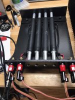
Here's one I made some 35 years ago. 4 x 8 ohm - 100w each.
Easy to configure for many values or channels.
Turned the rods to fit snug inside the resistors for support and some additional heatsinking.
It's been a very useful tool for both projects and repairs.
Easy to configure for many values or channels.
Turned the rods to fit snug inside the resistors for support and some additional heatsinking.
It's been a very useful tool for both projects and repairs.
Attachments

techtool, the concern is that the impedance of the dummy load can noticeably vary with frequency within the frequency measurement span. One relatively simple way to check that is to use a REW impedance measurement configuration and confirm flat-line magnitude and phase for a small metal film reference resistor, and then measure your dummy load to see if magnitude and phase vary.
The other concern with dummy loads is the voltage related distortion that can occur with load resistors that have a strong temperature coefficient of resistance and other non-linear operation (and I'd guess your WW Dales would not show up that aspect).
The other concern with dummy loads is the voltage related distortion that can occur with load resistors that have a strong temperature coefficient of resistance and other non-linear operation (and I'd guess your WW Dales would not show up that aspect).
Yes, I understand. I haven't used it for distortion measurements yet, as I am just beginning with REW, etc.
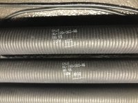
I know these are wire wound resistors so their inductance is likely to be a factor.
This was built (long ago) for power measurements and thermal testing.
When I get to the point where I'm confident with the results from REW, I'll test it as you suggested.
Thanks.
I know these are wire wound resistors so their inductance is likely to be a factor.
This was built (long ago) for power measurements and thermal testing.
When I get to the point where I'm confident with the results from REW, I'll test it as you suggested.
Thanks.
Waking this up again with a question, got pointed to this thread by someone who said i might get answers here. I am trying to use the quasy anechoic measurement technique in REW. However when trying to merge farfield with nearfield it seems that the trace arithmetic function always uses the window settings of the far field measurement. Does anyone now how this can happen/ how to fix it? every guide and every information i found pointed to the fact that it should just work, which it doesn't. I have already tried to up the merge frequency according to another post but no frequency works.

The merge result uses the 'B' windows, mainly in the expectation that will probably have wider windows to accommodate the LF response, but you can change them to whatever you like afterwards. The A and B measurements themselves have their own windows applied before the calculation happens.when trying to merge farfield with nearfield it seems that the trace arithmetic function always uses the window settings of the far field measurement
Sorry might have explained it wrong, english is not my first language 😉 so what happens is when i put the far field on A and the near field on B and merge them, the expected behaviour is that i get a full frequency response from 20hz. With the near field being the bottom end. The near field (so B) should not have a changed window. So how is it that when i merge i don't get a full response with the near field measurement filling in what the far field is missing.
In this graph: pink is near field, red is far field and green is combined
I did also try to change the window after the merge but then it just tanks like a pinguin trying to fly at the frequency that the merged result stops
What i meant with 'always' is that i also tried to change them around as a sanity check (so near field on A and far field on B) but that didn't work.
Last edited:
Difficult to say, best would be to attach a zipped mdat with the two measurements you are trying to merge. All very off topic for this thread though, would be better either in its own thread or posted on the REW support forum.
So I've been using this system for a couple weeks now and I just used it to reference the performance of some amps. repaired and built.
Not sure if I'm using it with the right preferences. I'm using a UCA202 with the prescribed load box and the latest REW software.
I did a Loop Back on the UCA202 at 1W and distortion measurements at the 20 watt level for Hafler DH-120 and a recently built MX50se.
What worked well was being able to adjust the DC balance distortion level (Not DC offset) on both channels of the Hafler (at 1w output).
AS for the Distortion settings, I chose the high pass filter and was not sure about the Manual Fundamental box. I also selected the default codec for input and output. I want to keep it simple but would appreciate any suggestions.
Attachments
-
 DH-120 Rt. Distortion 20W 5-23-23.png70.9 KB · Views: 149
 -
 DH-120 Lt. Distortion 20W 5-23-23.png71.6 KB · Views: 161
 -
 MX50 SE 1 Rt. Distortion 20W NO Manual 5-23-23.png63.9 KB · Views: 137
 -
 MX50 SE 1 Lt. Distortion 20W NO Manual 5-23-23.png64.3 KB · Views: 146
 -
 UCA202 Loopback 5-23-23.png69 KB · Views: 149
The DH-120 plots may be showing ground loop artifacts, whereby the amp input gnd (connected to the UCA202 output) is not the same point as the amp output gnd (connected to the UCA202 input), but rather the amp connects those two gnds internally through a link that has power supply noise on it.
Another possibility is a mains borne noise loop if your UCA202 and PC are not battery powered.
PS I think you meant '1V' not 1W for the loopback.
Another possibility is a mains borne noise loop if your UCA202 and PC are not battery powered.
PS I think you meant '1V' not 1W for the loopback.
Correct... The laptop and UCA202 are not battery powered. The DH-120 input is not a common ground to the output as on the MX50se.
Not really sure if that's an issue? I'll try batteries on the laptop. I think the UCA202 is USB powered.
Not really sure if that's an issue? I'll try batteries on the laptop. I think the UCA202 is USB powered.
Attachments
Some go to great lengths to remove mains frequency related signals as they want a very clean plot. If you know how and why they are in the plot, and that they don't affect the information you are after (eg. H2 and H3 levels) then perhaps no issue for you.
It is always worth checking how such signals 'get in'.
It is always worth checking how such signals 'get in'.
Here is the REW help: REW Help
Page 212 has information on Manual fundamental. No need to activate unless you are using a notch filter.
Comparing the MX50 plots to the DH-120 plots, it looks like the MX50 is well built with good control of noise whereas the DH-120 is noisy, perhaps due to issues with power supply design, layout, wiring, etc.
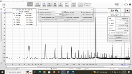
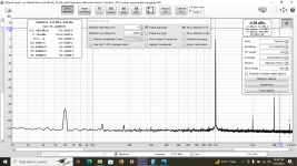
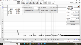
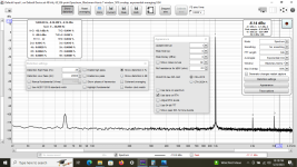
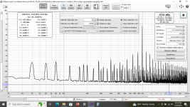
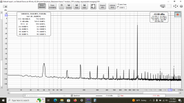
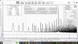
Here is a plot from an earlier MX50 SE that has some supply noise issues. After installing a different xformer and re-routing wires I seemed to be at a standstill.
I remembered something I read from the ESP site about the supply for the P101. Rod suggested installing .1 Ohm resistors between the parallel supply Caps. to reduce the higher harmonic noise artifacts. You can see this between the the 2 REW plots. Initial and fixed. Big difference.
I remembered something I read from the ESP site about the supply for the P101. Rod suggested installing .1 Ohm resistors between the parallel supply Caps. to reduce the higher harmonic noise artifacts. You can see this between the the 2 REW plots. Initial and fixed. Big difference.
Attachments

That is a big difference.
Adding a resistor to turn the C filter into a CRC filter will reduce the power supply ripple and amplifier noise. 0.1 Ohm is a good choice, probably 3 to 5W to keep the temperature down. So either a single resistor or parallel lower Wattage resistors.
Post some pictures of the amplifier. Perhaps there may be other things that can be done to reduce the noise.
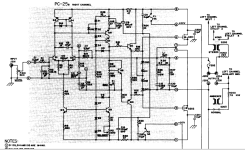
Given the MX50 SE is an amp module, then did you follow a power supply schematic and installation layout, or was that just diy ?
I'd say there was more going on than just inserting a 0.1 ohm, as the initial spectrum shows 40Hz harmonics, although the side-bands to the 1kHz show more expected 120Hz rectified artefacts.
I'd say there was more going on than just inserting a 0.1 ohm, as the initial spectrum shows 40Hz harmonics, although the side-bands to the 1kHz show more expected 120Hz rectified artefacts.
Adding the .1 Ohm 5W between the 2 6800 uF. caps (Neg. and Pos.) and re-installing the supply board gave me the second plot results.
Are you saying a 0.1 ohm was added in both the pos line and the neg line, between the bulk caps? Can you elaborate on 're-installing the supply board'? Was there also any change to the way you set up the measurement probes etc ?
- Home
- Design & Build
- Software Tools
- How to - Distortion Measurements with REW