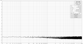
Thank you. What is voltage you are driving the amp - measure with DMM in AC volts mode. If you see it there in DMM, and don’t see it on REW display you may be looking at the wrong channel. Set the correct channel in the settings.
Then your amp is not playing any music. That’s zero output so not surprising you have not signal on FFT.
Try feeding it music from another source. You can find 1kHz test signal on YT even.
Try feeding it music from another source. You can find 1kHz test signal on YT even.
Artifacts in the REW spectrum may arise from any impedance/link between the amps input and output grounds (within the amp itself), as that forms a ground loop with the soundcard input-to-output ground link. If there are artifacts, then you may get some benefit from disconnecting the ground in the shielded cable between the amp and the soundcard input.
Your correct I'm not playing any music. I have no source connected to the amp, not even volume control.
Sorry I'm so dense. If I ever get it right I won't forget.
Sorry I'm so dense. If I ever get it right I won't forget.
Hi,
I stumbled over this thread after looking for a simple way to measure distortion in amps. Especially the Nelson Pass projects with one or two gain stages and mostly relative high second or third harmonics.
In these projects, the aim is often to get a certain amount of negative phase second harmonic. Is there a way I can see this in the REW measurements?
Do I aim for 180° phase next to the amount of second harmonic distortion shown in the RTA?
Is there a way to show the waveform of the distortion?
thanks,
William
In an RTA window with the 'Show Distortion' button active, and the soundcard generating a sine input (that is FFT locked to the RTA), and the soundcard inputing the amp's output, then the distortion harmonics are numbered and the measurement display box shows the HD levels and the phase can also be displayed (check box in RTA settings for Distortion settings). Example for a loopback RTA display below showing HD's and their phase measurements.
The Scope display only shows the amp's output signal. Likely that you would need a notch filter after the amp, and then to have that as input to the soundcard to display the HD waveform, although I 'see' more in a spectrum plot than I do in waveform.
The Scope display only shows the amp's output signal. Likely that you would need a notch filter after the amp, and then to have that as input to the soundcard to display the HD waveform, although I 'see' more in a spectrum plot than I do in waveform.
Attachments
Last edited:
In REW there is an option to display phase of harmonics. TBO, I do not think that this makes any difference.
Hi,
thanks for the answers although they don't really answer my question. What I would like to know is if the value of the phase standing next to the value of the second harmonic has to be 180° (or -180° which should be the same), to get what Nelson Pass refers to as negative 2nd harmonic distortion.
William
What I would like to know is if the value of the phase standing next to the value of the second harmonic has to be 180° (or -180° which should be the same), to get what Nelson Pass refers to as negative 2nd harmonic distortion.
William
Neither. What is considered negative phase H2 has phase shift by 90°, not by 180°. REW will show, what is negative phase second harmonic as 90° (no negative sign). Hopefully, this explanation will help:
https://www.diyaudio.com/community/threads/diy-aca-mini.379037/post-7177487
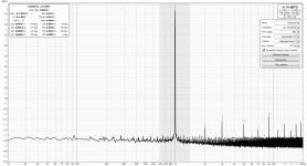
A laptop has benefit when using the 2i2 to measure a mains powered item of equipment. A self powered setup, like your loopback has no direct earth loop path to cause some hum ingress, however a clean sweep like yours does show the loopback cable and local setup is ok.
Also your harmonics and other artifacts appear to be nominal, so hopefully the other channel is similar. It can be worthwhile measuring the actual Vrms used for the loopback, and vary the signal levels so that you become aware of when distortion levels rise.
Also your harmonics and other artifacts appear to be nominal, so hopefully the other channel is similar. It can be worthwhile measuring the actual Vrms used for the loopback, and vary the signal levels so that you become aware of when distortion levels rise.
Last edited:
I will be checking other channel today. I need to put the Vrms in the notes for the plot(s). In this case it was 0.714 Vrms. Find that the 2i2 has more THD when > 0.74 Vrms, particular increase in the 2nd. Noise floor jumps when gain is increased to accommodate signals < 0.69Vrms and maintain -6 to 10DBFS on RTA.
I am quite happy so far, glad I saw this thread. My old setup was a EU 1616m. At the time it was quite good.
Is there a USB isolator that can lift the 2i2 ground path from the desktop?
I am quite happy so far, glad I saw this thread. My old setup was a EU 1616m. At the time it was quite good.
Is there a USB isolator that can lift the 2i2 ground path from the desktop?
I have a cheap eBay ADuM4160 based pcb with linear regulators that I power from a 12V battery on the soundcard side. It is USB1.1 (not USB2), but is able to lower mains earth related loop induced signals. However there are many ways for unwanted signals to ingress in to a spectrum, so there is often a need for care to suppress artifacts, and in some cases those signals don't actually matter to the measurement being made and are only aesthetically displeasing.
I think there is a more modern isolator around now, and I think pcb based modules aren't always on the market.
I think there is a more modern isolator around now, and I think pcb based modules aren't always on the market.
- Home
- Design & Build
- Software Tools
- How to - Distortion Measurements with REW


