jaddie, so your input was really 21dB below input clipping?
Not suggesting anything is a problem - just aiming to get a better 'picture' of performance 🙂
Not suggesting anything is a problem - just aiming to get a better 'picture' of performance 🙂
Did I really post that? I don't see it, but perhaps. According to Quantassylum, the sweetspot for THD with the QA401 is -16. I may have been at -21, but I didn't think so.jaddie, so your input was really 21dB below input clipping?
Not suggesting anything is a problem - just aiming to get a better 'picture' of performance 🙂
So, with the Qa401...here are the issues I see.
1. 60Hz and harmonic noise. One of the problems is that thing uses separate BNC connectors for each leg of the diff input. Hard to get great noise immunity without at tight conductor twist. I have some 6" BNC RG174 cables on the way, I'll twist those and see if it's any better.
2. USB power. I did change the USB cable, things got a little better, but the next move is a USB power injector to see if I can cure the 60Hz related noise. Sort of a disappointment, given the cost and otherwise good performance, that they didn't just do a DC connector and external PSU, if this was going to be an issue. The 60Hz+ harmonic spurs aren't something I see on any other interface.
3. The 20dB attenuator. I have a plot now showing better noise performance, still a -16 dBu input, but with the generator side running -2dBu. Sure it looks better, but it's a cheat. Also, when using this thing with REW, you have to set the attenuator in advance using a .toml file. Just sort of a pain, but the ASIO driver is from a third party, so nothing but a driver, not actual device control.
4. The input or output doesn't compensate for 6dB level increase with a differential signal. So, when you're generating -2dBu at the generator, it's really +4dBu. Confusing, and a potential gotcha that I don't see with other interfaces.
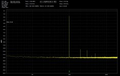
Here's what it looks like at -16dBu in, 20dB attenuator on, and the QA software, 128k FFT, 40 averages. I think this might as good as it gets.
Attachments
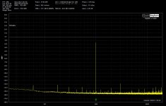
I just did a reset to the startup settings in the QA software, and put in a 6dB compensation for full differential loopback. BTW, the manual says that loopback testing should be single ended with the unused diff input shorted. Interesting. Anyway, two measurements, one with the 20dB attenuator off, one with it on. The software compensates for the level shift of the attenuator. You can see my noise issues with the attenuator off, but it's pretty nice with it on, though clearly and expectedly the noise floor comes up.
Attachments
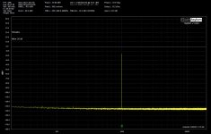
Here's the QA401 with REW. This is with the 20dB attenuator on. REW does not compensate for the attenuator, so the generator output is set to -2, and we get a bit under -18dBFS at the input. There is a 2dB discrepency in REW vs QA, not sure why. Can't do any actual meter measurements right now, but soon. The distortion products are probably at the output.
Attachments
Hi just testing the residual noise with my old asus essence stx (pcie) soundcard connected in my old HP z220 workstation.
3 tests.
Line input, input volume = 0, input volume = 50% and input volume = 100%
Also have a couple of USB interfaces that are nowhere near these numbers. BTW: Not at home, just testing with remote access to the machine.


3 tests.
Line input, input volume = 0, input volume = 50% and input volume = 100%
Also have a couple of USB interfaces that are nowhere near these numbers. BTW: Not at home, just testing with remote access to the machine.
Jaddie, your post #1,258 had the fundamental at -21.5 dBFS, so I thought that may indicate 0dBFS was your input clipping level.
I probably messed that one up.Jaddie, your post #1,258 had the fundamental at -21.5 dBFS, so I thought that may indicate 0dBFS was your input clipping level.
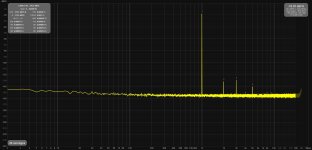
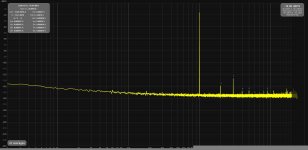
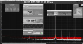
Here's the latest. I got a handful of 6" BNC RG174 cables. Took two and twisted them together. Clearly the 60Hz noise was inductive pickup from non-equal cables. 20dB attenuator is off. This is the problem with differential I/O with pairs of BNC connectors. Cabling must pretty much be custom. Just using BNC cables eliminates the twisted pair, which you must have for a differential input to really achieve high CMRR. So, how do you get a twisted pair from two BNC connectors? You have to make your own cables. It's just clumsy.
Wish they'd just make the box bigger and put XLRs on them.
The first one is with REW, the second with the QA software. The only difference is REW is set for 128K FFT, the QA set for 64K FFT. The reason is the QA software takes about 4X as long to perform one FFT, and averaging 40 tests my patience.
Attachments
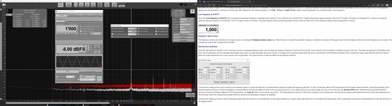
Those are impressive. Perhaps a little too impressive. One thing we should try to do when comparing noise especially is to standardize on settings. Longer FFTs will always slow lower noise because essentially the FFT bandwidth is smaller. Shorter FFTs will then show higher noise. John suggest using the V/√Hz axis option which is independent of FFT length, and exists only in the RTA, and is only meaningful when the spectrum choice is made. The result is a noise density graph. Also, we should pick a window an stick with it. Every window has a correction, a "scaling factor", to correct for the shape of the window. Every one except for the "Flat Top" choice, which is actually the choice John recommends. Unfortunately, the results are not in the familiar dBFS, or dBAnything, but instead are in V/√Hz on a log chart. That also implies careful voltage calibration before hand. A bit of a pain, but something that should be done anyway.Hi just testing the residual noise with my old asus essence stx (pcie) soundcard connected in my old HP z220 workstation.
3 tests.
Line input, input volume = 0, input volume = 50% and input volume = 100%
Also have a couple of USB interfaces that are nowhere near these numbers. BTW: Not at home, just testing with remote access to the machine.
The other thing is there's a single figure noise method using the SPL meter (again, calibrated first), where you can also look at weighting filters. Z is what we'd use for technical measurement comparison. Set for slow response too.
I get -111.9dBFS Z on the QA401.
Hi Xrk, hi john, hi everyone,I removed the ASIOAll driver and still no luck getting REW to respond to the 4i4 (with Focusrite ASIO driver). Clicking the ASIO control panel button in REW pulls up a Scarlett 4i4 3rd Gen Device Settings dialog which shows the firmware, hardware serial number, sample rate, buffer, and clock status which says “Synced”.
first... thanks a lot for the inspiration and the REW software. I had used it in the past for room correction but never for DUT audio anlysis. But as I had a Focusrite 4i4 anyhow for my Music hobby, I thought I give it a shot.
I did a quick loop test yesterday and I think it is ok(ish) but wondered if someone could cross-check and see if I caught everything incl. the RAT and generator settings.
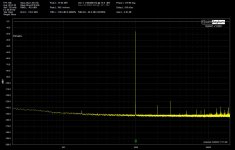
The 4i4 is speced with <0.002% THD+N and I got 0.0035% in at ca. 18dBFS input level (which is not even the sweetest spot but easy to replicate - Input 1 gain set to 0 and Output 1 potentiometer set to full) by using the internal DAC as signal generator and not fully elminating all main hum (see spike) influence.
Question: I set dithered to off, but couldnt observe a difference, when switching it on. What do you guys use - on or off?
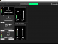
At Xrk: I hope you got your troubles with the ASIO driver sorted. For me it worked right from the get-go, but one needs to also have the app Focusrite Control installed to correctly route the inputs/outputs. See the picture below for my settings.
Thx. and please let me know what you think and if you need further details for my setup.
Cheers
Attachments
Hi HTHD,
Your setup appears to be working great. Nice job! You might be able to get lower THD if you use an external low distortion oscillator. The 2ppm 1kHz spice from Akitika is nice or the one from Victor here on DIYA is probably one of the best you can get. It’s below measurable by most equipment hence your will be linited by native distortion of the analyzer. But 0.001% is fine for most DIY projects.
Your setup appears to be working great. Nice job! You might be able to get lower THD if you use an external low distortion oscillator. The 2ppm 1kHz spice from Akitika is nice or the one from Victor here on DIYA is probably one of the best you can get. It’s below measurable by most equipment hence your will be linited by native distortion of the analyzer. But 0.001% is fine for most DIY projects.

Perhaps its because after working in audio for 50 years I've seen distortion measurement get so much better that I have this attitude. Distortion is about audibility. The audibility of THD is quite limited, not easily heard with music as the source, and easily masked by music signals. It's also harmonically related. We've been measuring somewhere around 40dB below audibility for quite some time, and any decent REW setup is capable of that. Time should be spent on attmepting to measure and evaluate other types of distorion, like IMD with muliple tones. The technique that I've found most interesting, especially when evaluating elusive ultra-linear devices like DACs and ADCS, is that outlined in Deane Jensens 1988 AES paper, "Spectral Contamination Measurement". I'm not sure John put in the generator capability because I asked, or if it just seemed like a good idea, but generating the test signals Jensen used is now trivial in REW. The resolution of the system in general exceeds that which he used for the paper, and even the filters he needed are not generally required today. All we have to do is do it. Download the paper, its quite interesting, though challenging. But I believe its the next frontier in meausring devices, now that everything is ruler-flat, with inaudible THD (except transducers, of course).
Thanks. Really appreciate for looking it over.Hi HTHD,
Your setup appears to be working great. Nice job! You might be able to get lower THD if you use an external low distortion oscillator. The 2ppm 1kHz spice from Akitika is nice or the one from Victor here on DIYA is probably one of the best you can get. It’s below measurable by most equipment hence your will be linited by native distortion of the analyzer. But 0.001% is fine for most DIY projects.
I saw the Akitika is still for sale. Not sure about the Victor one.
Did you get your 4i4 working? What values did you get?
Also interested in getting the latest Viktor's. I just don't know where to order.Thanks. Really appreciate for looking it over.
I saw the Akitika is still for sale. Not sure about the Victor one.
Did you get your 4i4 working? What values did you get?
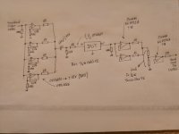
Today I had some measurements to make on a preamp section and I didn't want to go back to work to use the AP. It's more or less a cheap product so my soundcard performace was far enough for the job. The DUT had gain=1 and I wanted to have a 10Vrms output to stress it a little bit. My (now modded) E22 souncard has a nice unbalanced thd+n loopback of 0.0005% at 1k and I had a few parts lying around.
I came up with the schematic below and to my surprise the loopback with the circuit included was completely transparent at 1k (at least less than 0.0005% thd+n), which is what I needed for my measurements. So I thought it was interesting to share it. It showed increased distorsion in upper frequencies +10k compared to a "wire loopback" of course but an overall great performance. It also showed that running the soundcard dac/adc at it's sweet spot and amplifying/attenuating out of the box was the way to go, at least for my soundcard... 10Vrms was too much for the interface output anyways.
It reminded me that cables are extremely important especially for unbalanced connections, it needs to be short with a good amount of shielding copper around it and no ground loops. It is also preferable to power everything with batteries and stay far away from all sources of noise. Sadly I use a desktop PC so I tried to do my best by powering the amp/att circuit with batteries and no dcdc boost.
I used 5x9v batteries and TL431s to split the rails). Then i used a poor mans faraday cage (a metallic biscuit box) connected to ground with the amp/att circuit on batteries and the DUT inside. The DUT was powered by its own external wallmount psu.
This simple circuit is of course aimed at low power applications and should suit every soundcard available with the good amount of amp/att. There is a million ways to improve it but that was enough for my needs and my little home lab measuring capabilities.
As for the DUT, it was very, very bad. I knew that 10Vrms would be overkill of course but I wanted to be able to see the drama. Stay far away from the TL072/74 as well, it is also a source of noise 😆
Attachments
I'd suggest the best poor man's test oscillator is the soundcard itself with REW. There are a few forum threads on assessing how REW can null the soundcard induced tone distortion, and how that can be verified (within limits) using a notch filter (eg. https://www.diyaudio.com/community/...adc-and-dac-side-harmonic-distortions.381839/). Knowing your particular soundcard and how it performs both on the DAC and ADC sides is well worth the effort, and often leads to confidence in knowing you have an ok measurement setup.
Ah thanks for the hint. At first I didn’t understand how the compensation would work. But then had a look at the REW manual here (paragraph on Adding Distortion or in this case subtracting distortion).I'd suggest the best poor man's test oscillator is the soundcard itself with REW. There are a few forum threads on assessing how REW can null the soundcard induced tone distortion, and how that can be verified (within limits) using a notch filter (eg. https://www.diyaudio.com/community/...adc-and-dac-side-harmonic-distortions.381839/). Knowing your particular soundcard and how it performs both on the DAC and ADC sides is well worth the effort, and often leads to confidence in knowing you have an ok measurement setup.
https://www.roomeqwizard.com/help/help_en-GB/html/siggen.html#top
Have to try it probably next weekend as it sounds very interesting and straight forward to use.
I was not aware of the null function on REW. The previous measurements were done with Arta and with no software attempt to minimize thd at all except setting comfortable IO levels. At 24b 48khz the thd vs f plot in Steps wasn't even complete. It just gives an idea of what's going on.I'd suggest the best poor man's test oscillator is the soundcard itself with REW. There are a few forum threads on assessing how REW can null the soundcard induced tone distortion, and how that can be verified (within limits) using a notch filter (eg. https://www.diyaudio.com/community/...adc-and-dac-side-harmonic-distortions.381839/). Knowing your particular soundcard and how it performs both on the DAC and ADC sides is well worth the effort, and often leads to confidence in knowing you have an ok measurement setup.
My approach is that there's a lot of parameters to take into account for precision distorsion measurements (especially under 100dB) and I see my home made setup more like a pass/fail test device.
Software nulling might be an interesting way to achieve better precision but unfortunately I'm not experienced enough to understand how such compensation works in REW, designing precision notch filters is also quite a challenge in itself. To be very honest I'm too lazy to dig deeper into it and I trust the analog interface/software analysis/auto cal of the AP more than my soundcard and my cheap voltage dividers when it comes to precision. I'm pretty sure home-made stuff can challenge the best commercial audio analyzers though, but it's just a full time "hobby".
More info on Victors oscillator.
Specifications:
1kHz oscillator harmonic levels < -150dB
10kHz oscillator harmonic levels < -125dB
Output frequency nominal +/- 1%
Output voltage without load 300mV - 2.7V (RMS)
Output impedance 100ohm
External DC power supply 35V / 25mA
Dimensions (W x D x H) 60mm x 70mm (50mm - board) x 27mm
Weight 20g


https://viccc42.wixsite.com/uld-audio
http://archimago.blogspot.com/2022/01/using-victors-oscillator-as-reference.html?m=1
I use 4x 9v alkaline batteries in series for the ultimate in quiet 36v power supplies.
Specifications:
1kHz oscillator harmonic levels < -150dB
10kHz oscillator harmonic levels < -125dB
Output frequency nominal +/- 1%
Output voltage without load 300mV - 2.7V (RMS)
Output impedance 100ohm
External DC power supply 35V / 25mA
Dimensions (W x D x H) 60mm x 70mm (50mm - board) x 27mm
Weight 20g
https://viccc42.wixsite.com/uld-audio
http://archimago.blogspot.com/2022/01/using-victors-oscillator-as-reference.html?m=1
I use 4x 9v alkaline batteries in series for the ultimate in quiet 36v power supplies.
Thanks for all of your replies.
Just had some time and wanted to add some measurements for the Focusrite 4i4.
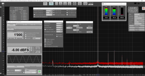
Best performance 4i4 loop-test with Onboard DAC (as above) but input level ca. -6dBFS: 0.0019% THD+N (Specs Focusrite <0.002).
Not bad considering the amateurish measurement setup.
Just had some time and wanted to add some measurements for the Focusrite 4i4.
Best performance 4i4 loop-test with Onboard DAC (as above) but input level ca. -6dBFS: 0.0019% THD+N (Specs Focusrite <0.002).
Not bad considering the amateurish measurement setup.
Attachments
Secondly, I tried the suggestion from trobbins from yesterday and used the REW "Add distortion" or better subtract distortion function. Very easy and straight forward to use.
The actual THD+N (still ca. 0.0035% with the same settings as posted last Sunday), did not get reduced but the the harmonics dropped by ca. 10 dB give or take. I wonder why the THD+N is not also reduced?
The actual THD+N (still ca. 0.0035% with the same settings as posted last Sunday), did not get reduced but the the harmonics dropped by ca. 10 dB give or take. I wonder why the THD+N is not also reduced?
Attachments
Looking at your numbers THD+N in your case is mostly noise (see N). Lowering harmonics does not lower noise.
- Home
- Design & Build
- Software Tools
- How to - Distortion Measurements with REW