The images internally from REW will bunch up the graph if you predefine a small size. On my laptop screen, they look OK and not bunched up at all.
Suffices that it works really well for me on a quickly breadboarded circuit tested today:


And digging deeper:

It was well worth developing a mod for significant reduction in THD for my soundcard.
This is going to be super useful.
Suffices that it works really well for me on a quickly breadboarded circuit tested today:
And digging deeper:
It was well worth developing a mod for significant reduction in THD for my soundcard.
This is going to be super useful.
hi,Ok folks seems my Autoranger now works and this is the setup I will use I thought I'd post some measurements. Note that Victors Oscillator isn't in its case and I'm using this psu to power it - http://tolisdiy.com/2019/03/11/low-thd-oscillator-power-supply-and-pcbs-as-case-panels/ both the autoranger and Victors are powered by battery powerbanks. The output of the Autoranger is set to 0.5v and I'm using the balanced input/output. Voltages out of victor are 0.5v, 0.7v, 0.8v 0.9v, 1v and full output 2.77v in order.
where did you get your oscillator from? i have found this web page: https://viccc42.wixsite.com/uld-audio
yet no response to my emails 🙂

I messaged Victor directly on herehi,
where did you get your oscillator from? i have found this web page: https://viccc42.wixsite.com/uld-audio
yet no response to my emails 🙂
Click the settings icon on the upper right, then from the new Window, click the Distortion settings. From that second window, you should be able to choose to display these.@YashN I see harmonic phase on your display, which I don't see on mine. I was hoping to see it. Maybe the window needs to be widened to see it?
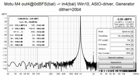
Pretty impressive, given that the gain amplifier inside the M2 (THAT 6263) is specified with a minimum THD+N of 0.0015% for symmetric signal.
Under the hood - line input of Motu M4 at a glance
To get an idea of the line inputs I opened the M4. This is done by removing the back panel first, then unscrew the for srews at the bottom (torx 9 shape) - and voila - a neat pcb appears with easy access to top and bottom side.So I wired a loopback feeding output4 @0dBFS into line input 4 and traced the signal with my scope. This is what I found:
Input is loaded by a 10k resistor, passes through 22uF elco and a 3.3kOhm series resistor into the inverting input of some unknown (very special!) pre-Amp. A feedback resistor of 1.2kOhm sets the gain to
G = 1.2/3.3 = 0.3636 V/V
The output of this pre-Amp is centered around +1.65V so this obviously drives the ADC-input directly. Let's do some math. Assuming
0dBFS-ADC-input = 2 x 3.3Vpp = 2 x 1,2Vrms. Total balanced input noise (pre-amp+ADC!) is about
N = -123dBFS = 1.64uVrms
Rg = 1.2kOhm || 3k3 = 880 Ohms and noise gain computes to120dB S/N at 3.3V supply voltage is definitely a challenge! To achieve this, the preamp must be driven with a quite low impedance and gain should be as low as possible. Here we find
G = 1 + 0.36 = 1.36 V/V
So, what are the results of that examination?
1. input impedance is 10kOhm || 3.3kOhm = 2.5kOhm.
2. Due to 3.3k series resistors inputs are robust against some overvoltage.
3. input caps are polarized in a way that does not block pos. input voltages.
4. to me this is a sophisticated design squeaked to the bleeding edge, no way to mod anything remaining here for me.
All in all it looks like the MOTU engineers did a superb job. Btw you will hardly find a better bang for the buck low THD+N op-amp than TI OPA1678.
Some people may wish to know the details of the electrolytic capacitors in the signal path. Brand, capacitance, voltage rating, manufacturer's model series (e.g. Panasonic "FR"), lead length, etc. Since those capacitors obviously contribute negligible measurable distortion.
I totally agree in that their contribution is neglible , and so I let the caps rollers do any further investigations.Since those capacitors obviously contribute negligible measurable distortion.
Let them copy your very successful choices. By telling them exactly what you chose, in great detail
Seems to be some misunderstanding. I described my soundcard as it came originally, no mods at all.Let them copy your very successful choices. By telling them exactly what you chose, in great detail
Seems to be some misunderstanding. I described my sound card as it came originally out of the box, no mods at all.
seems very similar to the input circuit of an M2:Under the hood - line input of Motu M4 at a glance
To get an idea of the line inputs I opened the M4. This is done by removing the back panel first, then unscrew the for srews at the bottom (torx 9 shape) - and voila - a neat pcb appears with easy access to top and bottom side.
So I wired a loopback feeding output4 @0dBFS into line input 4 and traced the signal with my scope. This is what I found:
Input is loaded by a 10k resistor, passes through 22uF elco and a 3.3kOhm series resistor into the inverting input of some unknown (very special!) pre-Amp. A feedback resistor of 1.2kOhm sets the gain to
G = 1.2/3.3 = 0.3636 V/V
The output of this pre-Amp is centered around +1.65V so this obviously drives the ADC-input directly. Let's do some math. Assuming
0dBFS-ADC-input = 2 x 3.3Vpp = 2 x 1,2Vrms. Total balanced input noise (pre-amp+ADC!) is about
N = -123dBFS = 1.64uVrms
Rg = 1.2kOhm || 3k3 = 880 Ohms and noise gain computes to
G = 1 + 0.36 = 1.36 V/V
So, what are the results of that examination?
1. input impedance is 10kOhm || 3.3kOhm = 2.5kOhm.
2. Due to 3.3k series resistors inputs are robust against some overvoltage.
3. input caps are polarized in a way that does not block pos. input voltages.
4. to me this is a sophisticated design squeaked to the bleeding edge, no way to mod anything remaining here for me.
All in all it looks like the MOTU engineers did a superb job. Btw you will hardly find a better bang for the buck low THD+N op-amp than TI OPA1678.
I don't think I mentioned the details about a simple mod I made in the Behringer UMC202HD thread to seriously improve THD for measurements with REW (or other).
This post gives the step-by-step modifications for the right channel.
Another member tried it on his card as well with great results.
In the same thread, a little earlier, you will find a simple mod by Alfred to disable the Phantom Power by removing an inductor (L4) as it causes higher order harmonic distortions and is never disabled even with the onboard switch at the OFF position.
Additionally, I have looked at the casing, and there are ways to improve the shielding. This post provides aditional details about what do to.
If you have this card or want to get one, these simple changes on it can provide a really good base for audio measurements for really, really cheap.
On the very first howto post you should not plug a TS jack into TRS out. It will short the inverting opamp output of the bal stage to gnd. Opamp will go current limiting and will generate distorsion. Also 100k is a very high value!!
Nice thread I learned a lot.
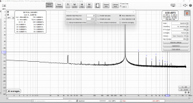
Here's my a Lynx E22 in loopback mode, I was searching for the best performing line out/in channel combo and the best output spot at 48k. it's around 1.5vrms
Cheers
Nice thread I learned a lot.
Here's my a Lynx E22 in loopback mode, I was searching for the best performing line out/in channel combo and the best output spot at 48k. it's around 1.5vrms
Cheers
Attachments
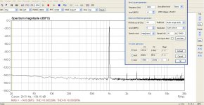
There is a plethora of thing that can go wrong with the measuring setup. I attach the loopback plot of my recently acquired MOTU M4 sound card.On the very first howto post you should not plug a TS jack into TRS out. It will short the inverting opamp output of the bal stage to gnd. Opamp will go current limiting and will generate distorsion. Also 100k is a very high value!!
Nice thread I learned a lot.
Here's my a Lynx E22 in loopback mode, I was searching for the best performing line out/in channel combo and the best output spot at 48k. it's around 1.5vrms
Cheers
Attachments
That's impressive! is that really at the full output of 0dBfs=+16dBu?There is a plethora of thing that can go wrong with the measuring setup. I attach the loopback plot of my recently acquired MOTU M4 sound card.
- Home
- Design & Build
- Software Tools
- How to - Distortion Measurements with REW