Understand. I can tell you that i operate this amp #1197 on my motu without damage, even with clipping signal. With a +-8V supply the amp output is at the limit specs for maximum input level for the motu.
I managed some fairly significant reduction of THD by modifying my soundcard. Currently though, I am limited here by having no preamp active before the inputs.
Now, I am looking for best practices to standardise some of my measurements for audio builds.
Are there any simple recommendations regarding FFT size, Windows, number of averages, and various sets of settings depending on use cases (quick check, deeper checks, ADC-related, DAC/Oscillator-related, etc...)?
For quick checks, i.e. near realtime, I usually do quite low FFT sizes (8k or 16k) and very few averages. Then I increase both of these and let it run for deeper checks.
YashN, I think your request is quite broad. As long as you use ASIO drivers, I have left everything @ default on REW and achieve 1ppm levels of loop back measurement. It makes sense to lower number of averages when setting up. Only other advice i'd give is keep the levels to the soundcard low (100 / 150mV RMS)
Thanks, I'll keep this in mind. I do use ASIO under Win. Under Linux, the system default drivers are used. The latter work very well.
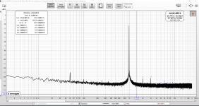
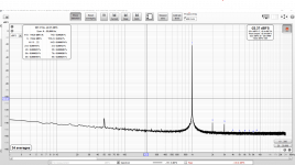
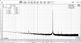
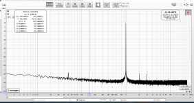
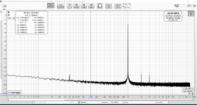
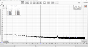
Ok folks seems my Autoranger now works and this is the setup I will use I thought I'd post some measurements. Note that Victors Oscillator isn't in its case and I'm using this psu to power it - http://tolisdiy.com/2019/03/11/low-thd-oscillator-power-supply-and-pcbs-as-case-panels/ both the autoranger and Victors are powered by battery powerbanks. The output of the Autoranger is set to 0.5v and I'm using the balanced input/output. Voltages out of victor are 0.5v, 0.7v, 0.8v 0.9v, 1v and full output 2.77v in order.
Attachments

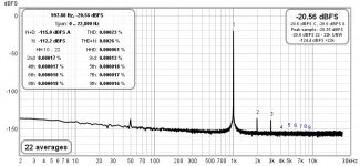

Some more detailed pics, voltages from Victors 0.34v, 0.4v, 0.5v, 0.6v, 0.7v, 0.8v, 0.9v. 1v and again full output 2.77v, Autoranger output to Motu in order 0.34v, 0.4v, 0.5v, 0.6v, 0.35v, 0.39v, 0.44v, 0.5v, 0.34v, pics are labelled
Attachments
-
 autoranger 0.34v victors 0.34v.png122 KB · Views: 145
 -
 autoranger 0.4v victors 0.4v.png115.9 KB · Views: 137
 -
 autoranger 0.5v victor 0.5v.png114.1 KB · Views: 132
 -
 autoranger 0.6v victors 0.6v.png124.1 KB · Views: 127
 -
 autoranger 0.35v victors 0.7.png127.7 KB · Views: 128
 -
 autoranger 0.39v victors 0.8v.png126 KB · Views: 119
 -
 autoranger 0.44v victors 0.9v.png128.7 KB · Views: 133
 -
 autoranger 0.5v victors 1v.png124.6 KB · Views: 129
 -
 autoranger 0.34v victors 2.77v.png122.6 KB · Views: 133
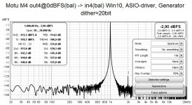
Today I received my brandnew MOTU-M4. After fiddling several hours with Linux I gave Windows🙁 a try, and after playing with the setting and some support from the internet.
https://panther.kapsi.fi/posts/2020-02-02_motu_m4I am happy to achieve a SINAD >100dB as expected
To make this work with windows installing the MOTU driver is mandatory - despite the "class-compliant USB", Haha!😛
https://panther.kapsi.fi/posts/2020-02-02_motu_m4I am happy to achieve a SINAD >100dB as expected
To make this work with windows installing the MOTU driver is mandatory - despite the "class-compliant USB", Haha!😛
Attachments
Last edited:

What I was asking a few posts ago was settings so as to 1. standardise my own measurements, and 2. standardise our general measurements so that they are repeatable and comparable.
As it is, everyone is using different settings. For sure, we have different hardware, but we could at least define a set of parameters which would allow some basis for comparisons. These would be very useful.
As it is, everyone is using different settings. For sure, we have different hardware, but we could at least define a set of parameters which would allow some basis for comparisons. These would be very useful.
For any kind of distortion measurements I propose a bandwidth limited to 20~20000Hz. Sampling rates, dither and signal levels should be chosen individually for best operating point of the audio interface.What I was asking a few posts ago was settings so as to 1. standardise my own measurements, and 2. standardise our general measurements so that they are repeatable and comparable.
As it is, everyone is using different settings. For sure, we have different hardware, but we could at least define a set of parameters which would allow some basis for comparisons. These would be very useful.
Today I received my brandnew MOTU-M4. After fiddling several hours with Linux I gave Windows🙁 a try, and after playing with the setting and some support from the internet.
https://panther.kapsi.fi/posts/2020-02-02_motu_m4I am happy to achieve a SINAD >100dB as expected
To make this work with windows installing the MOTU driver is mandatory - despite the "class-compliant USB", Haha!😛
What setting did you use? output levels, gain, etc.
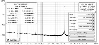
You find this info in the graph of #1210. Input4 is line input and has no gain setting at all. Actual input level is shown by REW as well.What setting did you use? output levels, gain, etc.
You find this info in the graph of #1210. Input4 is line input and has no gain setting at all. Actual input level is shown by REW as well.
I also have a MOTU M4 and I am able to replicate your setting. I was using input1 which has the gain. I have moved to the input4 now.
I think you set generator output to 0dB to get input to -2.xdB?
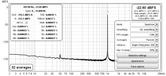
I was playing around with the windowing. Hann has the fattest main lobe. Audio Precision default is apparently similar to Dolph-Chebyshev which is much narrower.
I do not think so, as long as the amps you measure are worse...
Yes, output was 0dBFS. Until now I did not focus on the main lobe but on the total SINAD. Besides I think it is a good idea to come as close as possible to AP as this is the standard we have to compare to.I think you set generator output to 0dB to get input to -2.xdB?
I was playing around with the windowing. Hann has the fattest main lobe. Audio Precision default is apparently similar to Dolph-Chebyshev which is much narrower.
Makes sense for looking at audio band.For any kind of distortion measurements I propose a bandwidth limited to 20~20000Hz. Sampling rates, dither and signal levels should be chosen individually for best operating point of the audio interface.
It would be interesting to have settings for FFTs depending on use cases.
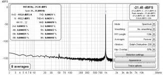
Increasing FFT-size lowers the noise floor making harmonic distortion better visible in the graph. You may play with all these parameters, and most of the time, you will try to "beautify" the graph. For that reason, FFT-graphs are a questionable way to compare things.Makes sense for looking at audio band.
It would be interesting to have settings for FFTs depending on use cases.
While playing, look at numbers, do they change? Most of the time they do not, and it is the numbers we will compare at the end, just as Amir does.
I think 16384 FFT bins is a good starting point.
Which is why some standard way of settings things up for more realistic figures and comparisons and depending on use cases is a necessity.For that reason, FFT-graphs are a questionable way to compare things.
I don't think it's questionable that much: it is a common way of visualising harmonic distortions.
Thanks for the size you mentioned, that kind of thing can be useful and is what I am looking for.
Specifying Windowing method depending on use case would be another requirement.
Specifying Number of Averages as well.
Broadly speaking, there are a few categories of use cases:
- Measuring various devices (ADC isn't the same thing as an oscillator)
- Measuring for a quick, but realistic overview
- Measuring for a deeper look, eating away at the real noise floor just to have a look at harmonics
- Measuring outside of audio band for resonances and proper THD values at higher frequencies
As you will never achieve a broader acceptance of a set of common FFT parameters, best practice is to focus on documenting the settings completely imho and have a look on what the pros do. And play with all of them to get a feeling of their relevance. In the real world there even exists no general accepted procedure to specify output power of audio amps, so how can you expect general rules for FFT-plots?Which is why some standard way of settings things up for more realistic figures and comparisons and depending on use cases is a necessity.
I don't think it's questionable that much: it is a common way of visualising harmonic distortions.
Thanks for the size you mentioned, that kind of thing can be useful and is what I am looking for
Specifying Windowing method depending on use case would be another requirement.
Specifying Number of Averages as well.
Broadly speaking, there are a few categories of use cases:
- Measuring various devices (ADC isn't the same thing as an oscillator)
- Measuring for a quick, but realistic overview
- Measuring for a deeper look, eating away at the real noise floor just to have a look at harmonics
- Measuring outside of audio band for resonances and proper THD values at higher frequencies
- Home
- Design & Build
- Software Tools
- How to - Distortion Measurements with REW