Oh, I'm sure it is my error - I just got the ADI and am not yet familiar with it.
The attached shows the setup; I'm using loopback cables on the rear of the ADI, Main outputs 1/2 into analog inputs.
On the ADI front panel the level is set at -6.0dB for Main Out 1/2 .
Any tips?
Jan
The attached shows the setup; I'm using loopback cables on the rear of the ADI, Main outputs 1/2 into analog inputs.
On the ADI front panel the level is set at -6.0dB for Main Out 1/2 .
Any tips?
Jan
Attachments
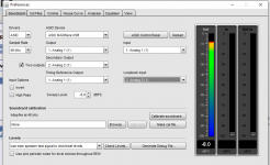
Make sure the ADI has selected USB, usually automatic if Basic Mode is set to auto, otherwise select Basic mode - USB.
OK, got it to work now. Also forget that you should activate a measurement, RTA or freq response, to activate the display in the Preferences screen. That might have been it.
Jan
Jan
REW at 32bit output/input to the sound device. Tested on linux alsa loopback for now, but should work for the USB audio gadget too (being my target).
To give it a bit of hard time a samplerate of 1,536kHz was used. Generator + RTA at 4M FFT takes about 80% of a single Intel core, REW being absolutely stable. Look at the precision of frequency and level detection.
John will kindly enable the 32bit IN/OUT in the next release. This change allows using a single level calibration 0dBFs <-> dbV in REW, while the 32bit samples can contain 24bit DAC/ADC data scaled for the currently used hardware range. No need to switch REW calibration when switching range in the HW analyzer. 10nV all to way to 10V in one sample. Of course it requires that the HW analyzer adjusts the DAC/ADC samples with a multiplier calibrated for the currently activated range, before sending to/after receiving from the REW audio interface. But that's a simple multiplication 🙂
Attachments
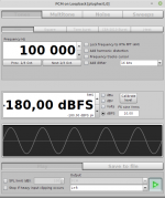
Yes, it is a digital loopback. The measurement shows that REW allows whole 32bit range of precision, even the LSB would be visible on the FFT. That allows sending 24bit samples scaled for the hardware range without having to change audio device calibration in REW when measurement range changes in the hardware. Two/three orders of magnitude of ranging, e.g. 22bits of real HW resolution + 10 bits for the ranging.
Yes, I am really happy that REW works so nice. Java has a reputation for being slow but it has gained many speed improvements throughout the years. Combined with John's experience, attention to detail, and incredible customer/user orientation it yields results. Writing REW in java gave it a multiplatform reach with very little effort, a very sound decision. Java sound drivers are open source (an easy to understand C, e.g. the alsa driver is jdk11u/src/java.desktop/linux/native/libjsound at master * openjdk/jdk11u * GitHub ) and JDK admins accept patches, making it a safe long-term investment.
If things get tough I am sure it will again be windows drivers and the windows sound layer. I have yet to test the 32bit usb-audio support in windows...
If things get tough I am sure it will again be windows drivers and the windows sound layer. I have yet to test the 32bit usb-audio support in windows...
Good evening! The 32bit sample-depth enhancement looks promising. But may I ask how you get the hardware-scaling integreted into the sample data?
As far as I understand it - please correct me i I am wrong - you will need a additional software layer between the aquisition hardware and REW to do the multiplication/scaling. Any plans, what route are you considering?
As far as I understand it - please correct me i I am wrong - you will need a additional software layer between the aquisition hardware and REW to do the multiplication/scaling. Any plans, what route are you considering?
My project involves the RPi Compute Module 4 placed on a board with the analyzer hardware, connected to the PC via USB-audio and USB-ethernet gadgets for data transfer to REW and control via a web browser. The hardware design has relay-switched calibration paths for level, frequency response, and harmonic distortions compensation of the input/output ranges.
Still many months to a (hopefully) working prototype...
Still many months to a (hopefully) working prototype...
Last edited:
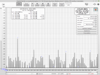
Hi guys, I tried to measure my amp but ran into a problem with the resistor divider. When I hook up the 8.2 ohm resistor and the 2k2/18k resistor divider to the sound card, even without the amplifier, I get a very big increase in distortion and noise floor. It's around -50dB with nasty harmonics all over (EMU1212 sound card is at -160dB with nothing connected).
This is actually down to the 2k2 resistor which is connected between + and -, I get the same effect if I only connect that resistor.
I tried connecting it both via balanced and mono TRS with same effect, and can't understand what is going on.
Any ideas?
I also tried to measure the amp at low levels without the divider, and it's better but still nowhere near what I would expect.
PS this is the dummy load resistor I got, 8.2ohm at 30w for 2.3eur a piece. Two of them in parallel for 4.1ohm.
PWR221T-30-8R20F Bourns | Mouser Croatia
Here's a quick scheme, nothing fancy, the same as most of you connect the amp for measurements.
But nevermind the full scheme, I'm getting tons of distortion and noise just by connecting that 2k2 resistor to my soundcard. According to the manual EMU1212 has 10k input impedance, maybe I should use different values of resistors?

But nevermind the full scheme, I'm getting tons of distortion and noise just by connecting that 2k2 resistor to my soundcard. According to the manual EMU1212 has 10k input impedance, maybe I should use different values of resistors?
I am not familiar with the EMU1212 (I have an 0404USB), but my guess would be you still have too much input signal and are seeing an overload condition on the input stage. I use 10K and 100 Ohms (100:1 ratio) in a balanced divider configuration. See this post:
Howto - Distortion Measurements with REW
Howto - Distortion Measurements with REW
Sounds like he is getting distortion with the resistor 2k2 resistor across the EMU1212 with no signal input.
Here's a quick scheme, nothing fancy, the same as most of you connect the amp for measurements.
But nevermind the full scheme, I'm getting tons of distortion and noise just by connecting that 2k2 resistor to my soundcard. According to the manual EMU1212 has 10k input impedance, maybe I should use different values of resistors?
View attachment 894801
How's the grounding done in that scheme?
Jan
Went back reread your first post. Make sure you have the resistor across pins 2 and 3. It sounds like you might have it hooked to ground on one end.
How's the grounding done in that scheme?
Jan
The ground is left floating, not connected to anything.
- Home
- Design & Build
- Software Tools
- How to - Distortion Measurements with REW