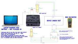
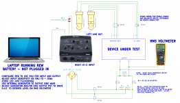
Here is a slightly updated sketch describing the correct resistor values for attenuation under different circumstances. I am also going to test using the XLR inputs because using those for differential signals bypasses the EMU's 5532 opamp input buffers in the signal path for the TRS inputs. Theoretically, this should slightly improve noise and distortion. I'll post a new sketch once I have tested this configuration. Your mileage may vary depending on the input circuitry of your interface.
Attachments
Last edited:
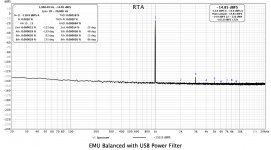
BTW - not sure if this has been covered before - but using a battery supply for your interface can greatly reduce noise, as opposed to the usual wall-wart. It also allows your setup to be completely floating (assuming you run your laptop on battery) and therefore avoid ground loops.
Since my old EMU runs on 5 VDC, I used this USB battery pack from Amazon to power it. It will power the EMU for about 10 hours.
Since my old EMU runs on 5 VDC, I used this USB battery pack from Amazon to power it. It will power the EMU for about 10 hours.
Attachments

Waiting for 8ohms 100W resistors to arrive to measure M2X with REW and Scarlett 2i2.
Meanwhile I wonder if there is any sense to make measurements using real loudspeakers as a load? Ok, the results would not be comparable to the "standard" measuments, but I would see the real performance of the amp in the real setup.
At least this would not make any harm to the loudspeakers, or would it?
Pass DIY Addict
Joined 2000
Paid Member
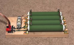
For power resistors, get four of these bad boys for $7 each.
Screw them down to a board side by side, wire them in parallel, putting a light switch between #2 and #3. Now you have a switchable load that is 200+ watts into 8 ohms and 400+ watts into 4 ohms. Then add a voltage divider set of resistors so you can run the output into your sound card.
Screw them down to a board side by side, wire them in parallel, putting a light switch between #2 and #3. Now you have a switchable load that is 200+ watts into 8 ohms and 400+ watts into 4 ohms. Then add a voltage divider set of resistors so you can run the output into your sound card.
Attachments
Well yes, that's a nice setup.
On the other side, if I measure at 1W (2.83V on 8ohms) on the output of the amp, Focusright 2i2 should be ok, as it allows max 22dBu (9.75V) on the line input on the minimum gain. Correct?
And what about measuring with the real speakers connected to the amp? Anyone tried that? Does it make any sense? Is it safe for the speakers?
-Alvis
I got very cheap chinese power resistors from ebay and placed them onto old CPU heatsinks (for free from a computer dump). With the heatsink fans turned on they can dissipate quite a load.
GitHub - pavhofman/speaker-adapter: Adapter for measuring amplifier outputs
GitHub - pavhofman/speaker-adapter: Adapter for measuring amplifier outputs
Last edited:
And what about measuring with the real speakers connected to the amp? Anyone tried that? Does it make any sense? Is it safe for the speakers?
Do you want yourself and everyone around to listen to the test signal? 🙂
@phofman, yea, I know 🙂 Could stand it for a minute at 1kHz 🙂 Providing it's safe to the speakers and I can play with the measurements 🙂
For power resistors, get four of these bad boys for $7 each...
During my sound reinforcement days, I used to use just one of these thingies and dip it in a bucket of water. Works wonderful 🙂
Here is a slightly updated sketch describing the correct resistor values for attenuation under different circumstances. I am also going to test using the XLR inputs because using those for differential signals bypasses the EMU's 5532 opamp input buffers in the signal path for the TRS inputs. Theoretically, this should slightly improve noise and distortion. I'll post a new sketch once I have tested this configuration. Your mileage may vary depending on the input circuitry of your interface.
For people using the EMU 0404, here is another setup using the XLR input vs. the phone plug. Internal THD is reduced somewhat since the 5532 input buffers are bypassed. Unfortunately, inherent noise does not change much - see the attached FFT of the EMU looped back to itsef. This also shows how to use the EMU output for single-ended or differential input devices under test.
Attachments
I tried those big green wirewound ceramic resistors and they generate a lot of self-distortion beyond what the amp would be like. When I switched to the EBG bulk metal power resistors, the distortion dropped significantly. This is detailed in my TPA3255 thread. The EBG UXP300 power resistors need a heatsink to work and you can use a simple computer CPU cooler. These can take 300w and have all their heat generated on a large flat surface that you mount a heatsink to.
ebay.com/i/223655655229
I think KOA BPR series resistors can work well too. They are also bulk metal non-inductive and are 5W. You can put 16x 0.5ohms in series to get 8ohms and 90w.
Last edited:
Pass DIY Addict
Joined 2000
Paid Member
XRK: Interesting observation! Thanks for the link, I'll check it out. I hadn't gone looking for distortion within the resistors themselves...
Hi! I did some experimentation with Focusright Scarlett 2i2 and measured my ACA and M2X. Got some strange results is one case and would be happy if the community could comment on that.
My setup was as follows:
- I used internal generator of RAW, set at -10dBFS, 1000Hz
- that gives about 360mV on the output of 2i2 with max monitoring volume, and it's not enough to get 2.83V on the output of ACA or M2X
- so I routed the signal via Shiit Magni 3+ pre-amp on 5.5x gain, setting the volume at the level that gave 2.83V measured on the output of the amplifier (it required 820mV output from pre-amp for ACA and 535mV for M2X)
- I am still waiting for the 8ohms 100W load resistors to arrive, so I measured with the actual speakers (Overnight Sensations) connected
- 2.83V signal from the output of the amp went (in parallel to the speakers) to the line input of the 2i2
- 2i2 line input can take up to 22dBu (9.75V), so I did not use any voltage divider network
- the gain of the 2i2 line input was set to minimum
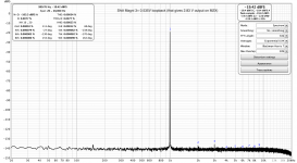
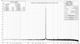
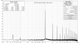
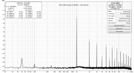
I got nice and consistent results on my ACA (see the 3 first pictures: Left channel, Right channel and the direct loopback from pre-amp to check that pre-amp did not introduce any significant noise or distortion). THD measured at 0.22% (much better than oficialy stated 0.7% distortion of ACA), and it is 2nd harmonic dominant, but I see the whole handful of other order harmonics, and mainly odd-order harmonics. Also notice that the phases of harmonics are very consistent between the channels (just 1-2 deg of difference between the channels). The hum from the mains is low and really not audible in reality.
With M2X I got mixed results that I do not fully undestand.
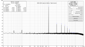
Left channel measured well and as expected. THD 0.022% (very close to "official" 0.025%), 3rd harmonics dominant with nice 2nd and a bit of 5th - very much as described by NP (my M2X is with the Tucson buffer now). Hum from the mains is very visible and this was also expected - neither toroid not the auto-formers are shielded yet in my M2X (waiting for the steel cover for the transformer and mu-metal for Edcors to arrive). This mains hum was actually the main reason of these measurements, as I wanted to see it before I make changes and then compare.
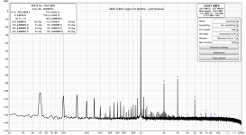
But on the right channel I am confused. Please see the picture (5th picture in the attachments). The overall noise floor rose by 25dBFS (from -130 to -105) hiding in effect much of the mains hum, and the harmonics look much different than on the left channel (and if you look at the phases of harmonics, they are totaly different than on the left channel - though in ACA measurement the phases matched almost perfectly between the channels).
What happens here? Why the increase in noise floor level?
I tried to change the loudspeaker used as a load, but same result. If you feed less V to the input, the noise floor on the right channel drops, but with inceasing levels of input the noise floor rises. But it does not rise on the left channel.
Does that hint to some problems in my M2X right channel? What could that be?
When listening to the music, though, I do not hear anything specific on the right channel, it plays as fine as the left to my ears.
Any ideas, please?
-Alvis
My setup was as follows:
- I used internal generator of RAW, set at -10dBFS, 1000Hz
- that gives about 360mV on the output of 2i2 with max monitoring volume, and it's not enough to get 2.83V on the output of ACA or M2X
- so I routed the signal via Shiit Magni 3+ pre-amp on 5.5x gain, setting the volume at the level that gave 2.83V measured on the output of the amplifier (it required 820mV output from pre-amp for ACA and 535mV for M2X)
- I am still waiting for the 8ohms 100W load resistors to arrive, so I measured with the actual speakers (Overnight Sensations) connected
- 2.83V signal from the output of the amp went (in parallel to the speakers) to the line input of the 2i2
- 2i2 line input can take up to 22dBu (9.75V), so I did not use any voltage divider network
- the gain of the 2i2 line input was set to minimum
I got nice and consistent results on my ACA (see the 3 first pictures: Left channel, Right channel and the direct loopback from pre-amp to check that pre-amp did not introduce any significant noise or distortion). THD measured at 0.22% (much better than oficialy stated 0.7% distortion of ACA), and it is 2nd harmonic dominant, but I see the whole handful of other order harmonics, and mainly odd-order harmonics. Also notice that the phases of harmonics are very consistent between the channels (just 1-2 deg of difference between the channels). The hum from the mains is low and really not audible in reality.
With M2X I got mixed results that I do not fully undestand.
Left channel measured well and as expected. THD 0.022% (very close to "official" 0.025%), 3rd harmonics dominant with nice 2nd and a bit of 5th - very much as described by NP (my M2X is with the Tucson buffer now). Hum from the mains is very visible and this was also expected - neither toroid not the auto-formers are shielded yet in my M2X (waiting for the steel cover for the transformer and mu-metal for Edcors to arrive). This mains hum was actually the main reason of these measurements, as I wanted to see it before I make changes and then compare.
But on the right channel I am confused. Please see the picture (5th picture in the attachments). The overall noise floor rose by 25dBFS (from -130 to -105) hiding in effect much of the mains hum, and the harmonics look much different than on the left channel (and if you look at the phases of harmonics, they are totaly different than on the left channel - though in ACA measurement the phases matched almost perfectly between the channels).
What happens here? Why the increase in noise floor level?
I tried to change the loudspeaker used as a load, but same result. If you feed less V to the input, the noise floor on the right channel drops, but with inceasing levels of input the noise floor rises. But it does not rise on the left channel.
Does that hint to some problems in my M2X right channel? What could that be?
When listening to the music, though, I do not hear anything specific on the right channel, it plays as fine as the left to my ears.
Any ideas, please?
-Alvis
Attachments
Hi Guys!
To determen a broken tweeter or not, can i use Sweep from 1m and compair them or do i need a 1khz beep from 5 inch?
What is the distortion praxis?
To determen a broken tweeter or not, can i use Sweep from 1m and compair them or do i need a 1khz beep from 5 inch?
What is the distortion praxis?
I just received my Focusrite Solo (3rd gen) and have a question about the loopback function. I connected the input to the output and can only get a -60 noise floor. Do you need to use the voltage divider with the loopback also? I also can't get the dBFS to go negative, making me think I'm overloading it and needing the divider.
Does the soundcard have an adjustable analog attenuator before the ADC? If not, have you considered generating the digital signal with lower magnitude?
Focusrite Scarlett Solo 3rd generation

Loopback at 980Hz using internal generator

Loopback at 1kHz using internal generator
Both of these had the laptop plugged in. I saw no difference plugged in or not.
Loopback at 980Hz using internal generator
Loopback at 1kHz using internal generator
Both of these had the laptop plugged in. I saw no difference plugged in or not.
RickRay, you may be able to discern your harmonics better from the noise-floor by playing around with the smoothing settings. It can be fun and a good learning curve to see how the harmonics change with signal level, as well as even play around with nulling out those harmonics using the generator function.
Gents, does anyone have experience with REW on an ADI-2 Pro Fs R? I can't get it to work; REW doesn't recognize the audio output from the ADI.
Jan
Jan
- Home
- Design & Build
- Software Tools
- How to - Distortion Measurements with REW