Yes, I use a CL60 between PG and SG.
Because this is a current feedback amplifier, the - speaker terminal and the GND could be on different potential.
But I will try your advice on "normal" amplifers.
Thanks for any advice.
Because this is a current feedback amplifier, the - speaker terminal and the GND could be on different potential.
But I will try your advice on "normal" amplifers.
Thanks for any advice.

If you are on Windows and if you are using a 24 bit sound card then you might want to try installing ASIO4ALL and then selecting "ASIO" drivers in the REW preferences/setup. (To enable 24 bits instead of 16 bits.)
Thanks, everyone.
Trobbins and kozard, I will try.
I have Scarlett Solo 3rd gen and 2i4 1st gen. Both are 24 bit I think.
Trobbins and kozard, I will try.
I have Scarlett Solo 3rd gen and 2i4 1st gen. Both are 24 bit I think.
Yes they are 24 bit interfaces. You might have the Focusrite ASIO driver installed already. Go to the REW preferences and see if there is an ASIO driver (instead of JAVA). If so try using the ASIO driver and try selecting 25 bit dither instead of 16 bit dither in the generator.
If not look at this Focusrite page and search for the text "make sure you select the Focusrite ASIO driver in the audio settings for that software"
How to install Focusrite drivers on Windows – Focusrite Audio Engineering
If not look at this Focusrite page and search for the text "make sure you select the Focusrite ASIO driver in the audio settings for that software"
How to install Focusrite drivers on Windows – Focusrite Audio Engineering
Before switching to a QA401 I had a scarlett 2i4. Wasn't to bad actually but you need to use an external attenuator to get the voltage down to the sweet spot which was 0.62v and I found the the output voltage was limited.
I did find that virtins multi instrument was alot better than REW.
You can download a trial and if you search the net it will tell you how to reset the trial period if you need to.
Multi-Instrument, a powerful multi-function virtual instrument software - Virtins Technology
Enjoy.
I did find that virtins multi instrument was alot better than REW.
You can download a trial and if you search the net it will tell you how to reset the trial period if you need to.
Multi-Instrument, a powerful multi-function virtual instrument software - Virtins Technology
Enjoy.
Before switching to a QA401 I had a scarlett 2i4. Wasn't to bad actually but you need to use an external attenuator to get the voltage down to the sweet spot which was 0.62v and I found the the output voltage was limited.
I did find that virtins multi instrument was alot better than REW.
You can download a trial and if you search the net it will tell you how to reset the trial period if you need to.
Multi-Instrument, a powerful multi-function virtual instrument software - Virtins Technology
Enjoy.View attachment 935987
Thanks,
I use a voltage divider.
The 2i4 1st gen has a better output, and the Solo 3rd gen has better input.
I used the Solo for the measurements.
Thanks for advice, I will try it.
Thanks,
I use a voltage divider.
That's actually not the best approach you can loose alot of drive current using a voltage divider. You are better off measuring the input impedance and then using a Pi filter.
If you can. The ultimate wiring setup in my opinion is putting a attenuator on the positive and negative inputs and then take your measurements differentially. This way you get rid of any common mode noise.
Also take care not to create a ground loop with the scarlett
Here is a link to explain it all in more detail.
QA401 - Differential measurements with attenuation - QA401 - QuantAsylum Forum
I also sorted the distortion issue on my amplifier as well it was the those doggy ebay load resistors.
Check out post 2444 here for the final results
diyAB Amp - The "Honey Badger"
diyAB Amp - The "Honey Badger"
Last edited:
If I understand it correctly you used an Ebay cement wire wound resistor with poor results? Did you end up with good results from the parallel & series combination of a number of those cement wire wound resistors? Or did you use a resistor different type in the end to get good results?
If I understand it correctly you used an Ebay cement wire wound resistor with poor results? Did you end up with good results from the parallel & series combination of a number of those cement wire wound resistors? Or did you use a resistor different type in the end to get good results?
Yes exactly what you said.
I'm going to use the parallel & series resistor array that I created as a baseline as I search for a solution with higher wattage as that current setup is only good for one or two short tests before taking a break to allow the load resistor to cool. I did order a few more of those resistors so I can make a 5x5 array.
Something to note with evey parallel string you reduce the inductance.
I was thinking of putting four 16 Ohm 100W aluminum case resistors in parallel to get 4 Ohms. I wonder if that is a good configuration for low inductance.
Do you have a way to measure the inductance? If not you might like to purchase a few of these to use as a baseline to complete the other resistor you are considering.I was thinking of putting four 16 Ohm 100W aluminum case resistors in parallel to get 4 Ohms. I wonder if that is a good configuration for low inductance.
I ended up with 1uH.
But its not just about that. As keantoken said in my thread its about how the magnetic field from the collapsing inductance injections more harmonics into the measured signal.
AU $2.46 5%OFF | 10pcs 10W 5% Cement Resistor Power Resistance 0.1 ~ 10K 0.1R 0.5R 10R 50R 0.22 0.33 0.5 1 2 5 8 10 15 20 25 30 100 1K 2K 3K ohm
10pcs 10W 5% Cement Resistor Power Resistance 0.1 ~ 10K 0.1R 0.5R 10R 50R 0.22 0.33 0.5 1 2 5 8 10 15 20 25 30 100 1K 2K 3K ohm|Resistors| - AliExpress


Last edited:
I am curious if I can find any tables with inductance versus resistance for 10W, 20W or 50W wire wound resistors. I wonder what the optimal value is for the lowest ratio of inductance to resistance.
Last edited:
I wonder what the inductance would be of a four Ohm version of this:
500W Aluminum Power Metal Shell Case Wirewound Resistor 0.1R ~ 500R 0.1 0.5 1 2 4 5 8 10 50 100 200 500 ohm|Resistors| - AliExpress
I wonder if I can find reasonably affordable metal oxide that can be paralleled to a high enough power:
500W Aluminum Power Metal Shell Case Wirewound Resistor 0.1R ~ 500R 0.1 0.5 1 2 4 5 8 10 50 100 200 500 ohm|Resistors| - AliExpress
I wonder if I can find reasonably affordable metal oxide that can be paralleled to a high enough power:
Inductance for different resistor types:
Resistor type Inductance
Wirewound 0.03 – 56 μH
Foil <0.08 μH
Metal oxide 3 – 200 nH
Film <2 nH
Last edited:
Personally I was looking at this as its spec is low inductance.I wonder what the inductance would be of a four Ohm version of this:
500W Aluminum Power Metal Shell Case Wirewound Resistor 0.1R ~ 500R 0.1 0.5 1 2 4 5 8 10 50 100 200 500 ohm|Resistors| - AliExpress
284-NHS200-8.0F NHS200 8R0 1% ARCOL / Ohmite | Mouser Australia
But I'm now cautious of the metal casing. But have an enquiry in with mouser to get the exact inductance.
I have also been looking at this.
100W 8 Ohm(8R) inductive Resistor Tube Power Audio Amplifier Test Dummy Load 1Pc | eBay
Or this
1000 WATT 8 ohm test DUMMY LOAD non inductive for audio amplifier | eBay
I don't really want to put that many in parallel but Metal Oxide is supposed to be much lower inductance:
50pcs 5W Metal oxide film Resistor 5% 1R ~ 10M 100R 220R 330R 1K 2.2K 3.3K 4.7K 10K 22K 47K 100K 1M 100 220 330 ohm Carbon Film|Resistors| - AliExpress
50pcs 5W Metal oxide film Resistor 5% 1R ~ 10M 100R 220R 330R 1K 2.2K 3.3K 4.7K 10K 22K 47K 100K 1M 100 220 330 ohm Carbon Film|Resistors| - AliExpress
True, I just used what I had. For now its a baseline to compare as I seek out a better alternative.I don't really want to put that many in parallel but Metal Oxide is supposed to be much lower inductance:
50pcs 5W Metal oxide film Resistor 5% 1R ~ 10M 100R 220R 330R 1K 2.2K 3.3K 4.7K 10K 22K 47K 100K 1M 100 220 330 ohm Carbon Film|Resistors| - AliExpress
Last edited:
That's actually not the best approach you can loose alot of drive current using a voltage divider. You are better off measuring the input impedance and then using a Pi filter.
If you can. The ultimate wiring setup in my opinion is putting a attenuator on the positive and negative inputs and then take your measurements differentially. This way you get rid of any common mode noise.
Also take care not to create a ground loop with the scarlett
Here is a link to explain it all in more detail.
QA401 - Differential measurements with attenuation - QA401 - QuantAsylum Forum
That's my simmetrical voltage divider = attenuator.
I also sorted the distortion issue on my amplifier as well it was the those doggy ebay load resistors.
Check out post 2444 here for the final results
diyAB Amp - The "Honey Badger"
diyAB Amp - The "Honey Badger"
Thats my attenuator = simetrical voltage devider
Attachments
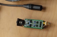
Good work.Thats my attenuator = simetrical voltage devider
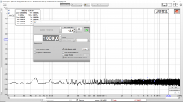
Can you give me some numbers?
Amplifier output voltage Vrms or Vpk-pk
And your target input voltage which you possibly attained through loopback testing to get the lowest distortion levels
Mine was 630mv rms
Also have you measure your input impedance of your scarlett.
Mine was 13,675 ohms
Last edited:
- Home
- Design & Build
- Software Tools
- How to - Distortion Measurements with REW