This should be easy to measure using a dome driver that is sealed, like a 2 inch dome mid. Suspend one in the air and measure its response and compare to a second one mounted on a baffle, A-B them. And also listen for changes in tone.I need to add that if you are thinking and looking at real driver measurements and especially only single axis frequency response, it might be hard to differentiate between effects of diffraction and other issues like cone breakup. However if you inspect this stuff with ideal driver effects of diffraction are plain visible and easy to judge.
Frequency response of idela transducer would be flat (sans beaming) if it was only direct sound from the transducer. Any deviation from this is due to at least one another delayed sound source making interference like sone reflection, resonance or diffraction. The longer the delay the lower in frequency interference is seen in a frequency response plot.
It will show the audible effect of the diffraction and the FR can also be measured. The driver in free air will have as little diffraction as possible, only that caused by whatever mounting plate is around it. "Subtract" if you will the measurements of the baffled driver from the free air placed one, and that difference is the diffraction effect. I rarely see this done.
The third element that can be added is an actual instrument. A clarinet for example has a FR from about 150 - 1850 Hz, with harmonics above that. Select a FR driver that you like for accuracy, baffle it with a sphere, then also a more conventional baffle enclosure, and then have someone who is a clarinet player play a short tune from a good recording of a single clarinet. At same amplitude in a decent room, play all three and compare.
The third element that can be added is an actual instrument. A clarinet for example has a FR from about 150 - 1850 Hz, with harmonics above that. Select a FR driver that you like for accuracy, baffle it with a sphere, then also a more conventional baffle enclosure, and then have someone who is a clarinet player play a short tune from a good recording of a single clarinet. At same amplitude in a decent room, play all three and compare.
An invalid premise.The driver in free air will have as little diffraction as possible
dave
You say this, but only now do I see a question...Sir, you could elaborate what is wrong and give a lesson because I and many of us are here to learn the craft.
The answer is that I see diffraction being conflated with the simple geometric properties of the things being simulated. This is expected for the simulation type you are using. Just because you can't see it, doesn't mean the diffraction has gone away.
On what basis? The sound from the mouth of a clarinet is played in free air, not through a baffle (imagine the clarinet being played through a hole in a baffle). So a good sealed domed driver (not a cone) that needs no baffle and can be placed in free air (hang it from a rod in the ceiling) and plays the clarinet, all other things equal, has as little diffraction as possible vs. the actual instrument.An invalid premise.
dave
doesn't mean the diffraction has gone away.
I expect there are no cases where diffrction is not present. Unless the loudspeaker is flush mounted in an infinite wall (no place for you to sit).
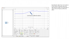
Our goal is to minimize it. A sphere helps, a teardrop is better, but the actual optimum size is related to frequency. But even a “perfect” shape would still have 2π to 4π transition. That of your naked 2” midDome will have significant HF edge diffraction and significant ripple at the 2π to 4π transition.
dave
Can't use a flat wall - needs to be spherical, or a tear drop as you say may be better but wasn't tested by Olsen and is almost impossible for a DIYer to make. The edge diffraction of a hemispherical diaphragm will be less than a cone shaped speaker mounted in some kind of baffle, as long as the mounting plate of the dome is not excessive (some are).I expect there are no cases where diffrction is not present. Unless the loudspeaker is flush mounted in an infinite wall (no place for you to sit).
Our goal is to minimize it. A sphere helps, a teardrop is better, but the actual optimum size is related to frequency. But even a “perfect” shape would still have 2π to 4π transition. That of your naked 2” midDome will have significant HF edge diffraction and significant ripple at the 2π to 4π transition.
dave
Here is an interesting short video with an easy experiment, a guy mounts a Dayton 1 1/8" dome tweeter (neo motor) - not real expensive but not bad FR curve just peaks about 4 db above 86 db eff. at around 2,000 Hz. He first uses a conventional flat baffle maybe 8" wide and mounts the driver flush. Then uses a recessed conical mounting with the same driver, Compares the FR, red and green (the latter is the recessed mount). Instead of a 5 db max difference (vs. a flat FR) the red peaks about 4 dbaround 2 kHz and then dips about 1 db around 15 kHz), you get a whopping 13 db max difference in the green FR graph using the recessed cone. Ughhh.
He doesn't measure the driver using a rounded edge flat baffle nor in free air. But the difference is due to the baffle itself and this is a diffraction effect. Here the cone shaped recess itself is causing a huge problem. For all the fans of horns, I would say this is not a positive thing. This is similar to cupping your hands around your mouth while singing. So domes and spherical enclosures avoid this.
He doesn't measure the driver using a rounded edge flat baffle nor in free air. But the difference is due to the baffle itself and this is a diffraction effect. Here the cone shaped recess itself is causing a huge problem. For all the fans of horns, I would say this is not a positive thing. This is similar to cupping your hands around your mouth while singing. So domes and spherical enclosures avoid this.
A sphere diffracts. Smoothly, but it does. An infinite wall has no place to defract.Can't use a flat wall - needs to be spherical
So? B&W did the research. Not really any harder than making a sphere.a tear drop as you say may be better but wasn't tested by Olsen
dave
Hey, that guy is a local hifi buddy. No dummy. aka Hollywood.Here is an interesting short video...
dave
PS: 9 min is long.
You're jumping to (dangerous) conclusions. I'd say read up about horn techniques and learn why they raise output. (I'm sure there are beter sources to explain this on this forum itself)Here is an interesting short video...
While I would agree the horn shape in this video causes diffraction, I wouldn't jump to the conclusion and blame every horn for having similar problems...
Find out why horns have more output. Yes, the output of a horn needs help to restore the FR shape but one can design a horn that has (very) little diffraction, same as one can design an enclosure to have little diffraction. A driver without a baffle still suffers from diffraction though. It still has edges that can diffract, if the waves "see" those edges (but that's another story).
P.S.
The horn thread I linked to is an ongoing investigation to horn shapes with (among other subjects) special interest in low diffraction. While it's very long with many posts, it is an awesome thread with information for more than horn lovers alone. It is an investigation of shapes and their influence on waves. Even when your interest lies elsewhere, it is a useful read.
Last edited:

Not according to Olsen's charts or the research done by Cabasse, Demand Better Audio, Reckhorn or Gallo (and other high end manufacturers). The sound waves do diffract off of a flat surface and practically speaking, we don't mount speakers in walls 🙂A sphere diffracts. Smoothly, but it does. An infinite wall has no place to defract.
So? B&W did the research. Not really any harder than making a sphere.
dave
Thanks for the the thread mention. Of course yes horns do raise amplitude (why cheerleaders at ball games use them 🙂 and due to sound pressure vs. shape, but often unevenly across the spectrum of frequencies. They are more efficient to be sure (so their popularity early on as hi fi emerged in the 50s but we had smaller powered tube amps). But today when transistor amp power is plentiful (I know some like tubes) we don't inherently need horns for amplitude. Beyond 95 db consistently anyway can damage hearing long term. `You're jumping to (dangerous) conclusions. I'd say read up about horn techniques and learn why they raise output. (I'm sure there are beter sources to explain this on this forum itself)
While I would agree the horn shape in this video causes diffraction, I wouldn't jump to the conclusion and blame every horn for having similar problems...
Find out why horns have more output. Yes, the output of a horn needs help to restore the FR shape but one can design a horn that has (very) little diffraction, same as one can design an enclosure to have little diffraction. A driver without a baffle still suffers from diffraction though. It still has edges that can diffract, if the waves "see" those edges (but that's another story).
P.S.
The horn thread I linked to is an ongoing investigation to horn shapes with (among other subjects) special interest in low diffraction. While it's very long with many posts, it is an awesome thread with information for more than horn lovers alone. It is an investigation of shapes and their influence on waves. Even when your interest lies elsewhere, it is a useful read.
(most of) The copies of Olson’s results you refer to is a scan i made decades ago. This one?Not according to Olsen's charts ...
The point of the chart is to show the nature of the 2π to 4π transition. The sphere is just really smooth, but you still have a 6dB loss in output.
dave
There are more reasons than raised output alone why horns can be an interesting choice. Should be easy to find those reasons too 😉.
The thread I linked to is an example, there are a lot of mentions of waveguides instead of horns, as the main interest isn't always to raise efficiency.
Directivity control certainly being one of the beneficial features of interest.
Notice the the use of "a narrow aperture" and "across an edge" in this explanation of the word diffraction. That should put things more into perspective.
A sphere could be seen as a horn that is bent backwards. A baffle as a 180 degree horn. So what makes one smoother than the other? The way it ends or transitions... A horn with a mouth round-over or a sphere or egg shaped enclosure. They all soften the effects of diffraction, how much depends on their size compared to the wave length. Technically, even the surround of a driver is a source of diffraction. Another edge the wave goes across....
Look how B&W and other manufacturers like Genelec and Kef work hard to minimize the influence of their surround.
Looking at a dome shaped driver, you still see ridges or edges when looking at the dome to sphere transition. An inflating/deflating balloon shaped driver would be sort of ideal 😀. I believe it has been tried...
The thread I linked to is an example, there are a lot of mentions of waveguides instead of horns, as the main interest isn't always to raise efficiency.
Directivity control certainly being one of the beneficial features of interest.
diffraction
/dɪˈfrakʃn/
noun
the process by which a beam of light or other system of waves is spread out as a result of passing through a narrow aperture or across an edge, typically accompanied by interference between the wave forms produced.
Notice the the use of "a narrow aperture" and "across an edge" in this explanation of the word diffraction. That should put things more into perspective.
A sphere could be seen as a horn that is bent backwards. A baffle as a 180 degree horn. So what makes one smoother than the other? The way it ends or transitions... A horn with a mouth round-over or a sphere or egg shaped enclosure. They all soften the effects of diffraction, how much depends on their size compared to the wave length. Technically, even the surround of a driver is a source of diffraction. Another edge the wave goes across....
Look how B&W and other manufacturers like Genelec and Kef work hard to minimize the influence of their surround.
Looking at a dome shaped driver, you still see ridges or edges when looking at the dome to sphere transition. An inflating/deflating balloon shaped driver would be sort of ideal 😀. I believe it has been tried...
Last edited:
Yes these are Olson's charts, all of the charts show a lower output below 300 Hz, it may have been the driver he was using. The key point is the sphere alone (but not the hemisphere) did not affect the FR in the important mid and lower high ranges. Meanwhile the driver end-mounted in a cylinder was the worst, along with a cube. So it calls into question IMO that speaker design with drivers mounted on cylinders at a right angle.
Last edited by a moderator:
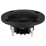
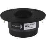
Yes some drivers have large mounting plates. The Dayton 1" dome tweeter ND25TA-4 with nd motor is pretty small vs. the Dayton 1-1/8" RST28A-4 with a traditional ferrite magnet. The type of motor makes a difference.There are more reasons than raised output alone why horns can be an interesting choice. Should be easy to find those reasons too 😉.
The thread I linked to is an example, there are a lot of mentions of waveguides instead of horns, as the main interest isn't always to raise efficiency.
Directivity control certainly being one of the beneficial features of interest.
Notice the the use of "a narrow aperture" and "across an edge" in this explanation of the word diffraction. That should put things more into perspective.
A sphere could be seen as a horn that is bent backwards. A baffle as a 180 degree horn. So what makes one smoother than the other? The way it ends or transitions... A horn with a mouth round-over or a sphere or egg shaped enclosure. They all soften the effects of diffraction, how much depends on their size compared to the wave length. Technically, even the surround of a driver is a source of diffraction. Another edge the wave goes across....
Look how B&W and other manufacturers like Genelec and Kef work hard to minimize the influence of their surround.
Looking at a dome shaped driver, you still see ridges or edges when looking at the dome to sphere transition. An inflating/deflating balloon shaped driver would be sort of ideal 😀. I believe it has been tried...
Attachments
Skfisher, I think we might have a problem with terminology.
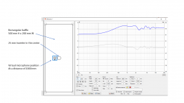
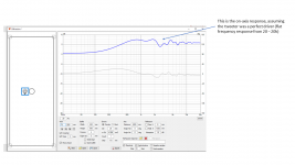
I put together some graphics to explain it. This is a simulation of a simple 500 mm x 200 mm box, with a standard 25mm tweeter in the middle. This simulation assumes the tweeter is an ideal perfect driver, so it has a flat frequency response from 20 Hz to 20 kHz.
So this is what is meant when we say that
J.
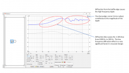
That lower output below 300 Hz is the result of diffraction. Diffraction is not just the high frequency ripple. It is also the drop in SPL as the frequency decreases. The driver transitions from 2-pi to 4-pi radiation. The shape and frequency of the transition from 2-pi to 4-pi is actually more important to crossover design than the high frequency ripple is... even though the high frequency ripple looks quite alarming.Yes these are Olson's charts, all of the charts show a lower output below 300 Hz,
I put together some graphics to explain it. This is a simulation of a simple 500 mm x 200 mm box, with a standard 25mm tweeter in the middle. This simulation assumes the tweeter is an ideal perfect driver, so it has a flat frequency response from 20 Hz to 20 kHz.
So this is what is meant when we say that
The sphere still has the transition from 2-pi to 4-pi radiation, and with it comes a -6 dB drop in SPL.A sphere diffracts. Smoothly, but it does.
J.
Attachments
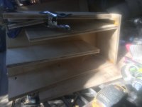
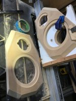
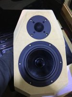
Best i (not saying much) could do with the dayton rs series
Attachments
-
 DB35F399-64B1-44AB-AA58-76AFD05AB91A.jpeg334.5 KB · Views: 103
 -
 250303DB-ECA8-4FDD-ABCF-96419A2FBAB4.jpeg520.7 KB · Views: 111
 -
 46EDD12F-566A-4774-9A14-2CB6FDA5473C.jpeg245.9 KB · Views: 97
 -
 F5A0CDA9-F33E-4EEE-ADCC-74DF64DF5BB9.jpeg463.9 KB · Views: 104
 -
 154D903B-E90E-4843-884E-6CE62549AECF.jpeg369.2 KB · Views: 124
- Home
- Loudspeakers
- Multi-Way
- How to build a spherical speaker?