The studio could be like an anechoic chamber, your room at home won't. Yes placement and room type have huge effect, but you want to at start with speakers that avoid diffraction, that introduces yet another element that will affect the sound. Unless you want to say the folks at Gallo Acoustics, Cabasse, DBA and other manufacturers that recognize the importance of diffraction are wrong?Wrong thinking i.m.h.o... what you add with that free standing speaker is the reflections of the space the speaker is in. Your room.
What's done in a studio with in wall speakers is to avoid adding to the sound that is recorded for mixing/mastering. They go to great length to get to listen to the recording without the added effects of the room they are in. Depending on the studio philosophy I must add, there's more than one.
You seem to want to add your room's signature to the recording and call that more faithful. It can't be more faithful, although it could be more pleasurable to your ears.
The studio could be like an anechoic chamber, your room at home won't. Yes placement and room type have huge effect, but you want to at start with speakers that avoid diffraction, that introduces yet another element that will affect the sound. Unless you want to say the folks at Gallo Acoustics, Cabasse, DBA and other manufacturers that recognize the importance of diffraction are wrong?
I've never said that, in fact, I have build my own speakers to have low diffraction ripple. But the ultimate way to achieve that would still be that infinite wall.
But we can't have that, as there will be a floor, ceiling and side walls etc... Yet, there are more options than the sphere shape alone. As said, you can also achieve it with the right shape horn, or an egg shaped enclosure like I have.
My room does have damping panels to specifically absorb early reflections, as I want to hear the recording, not my room. I don't want the anechoic space of a studio, so I've added a Haas kicker for my listening pleasure. But I did create a reflection free zone (not completely free, but certainly reduced) like is used in a studio.
The added lateral arriving late energy gives me the illusion of being in a bigger space than really I am. But the recording itself gives me the illusion of space. Not my (too small) living room.
IR as measured at the listening spot, far left is the IR peak, then about ~17 to 20 ms of a reflection reduced zone (-20 dB), followed by the Haas kicker.
Without the Haas kicker:
Recorded at the same spot, just without the Haas kicker. The reduced early reflections allow me to listen to room queues as recorded
instead of listening primarily to my own room. A studio would drop down about 30 dB though after the initial peak, no contest there.
It still is a relatively normal living room.
Last edited:
I don't know what you are after but I've demonstrated the stuff many many times during past 10 months or so but its not my invention. All I'm saying you can observe the effects directly from the frequency response when there is more and when there is less effects seen. This doesn't say when its audible, only that its more likely audible when there is ripple seen in frequency response. Its just common sense, otherwise the frequency response plot would be meaningless.Do you have evidence of this?
Come on you are intelligent person and I'm not sure what you are after. If you have studied edge diffraction and have come up to other conclusion please reveal it so we can have discourse on the stuff.
I do not have any definitive source for you but you can do research on it, google up and numerous results come up, Linkwitz site is among the first results for example.
Here again, simplified, read it up dont skip it TLDR like you have before. Its based on the concept that edge diffraction makes the edge secondary sound source:
Primary source is our transducer, a point source on a baffle and the secondary source at the edge is a line source with varying delay depending on the geometry of the baffle, distance from edge to our point source transducer. Now, the closer the edge is, the shorter the distance from point source to edge, the higher up in frequency we see interference on a frequency response plot. Also, the higher the frequency the less there is sound toward the edge due to our transducer beaming. Hence, as edge is closer to source the delay be omes less and eventually it would become one with the transducer, zero. Our real world transducers have some rims so delay doesn't go to zero but very low nevertheless.
Actual numbers, geometries and what not can be measured, calculated, simulated, what ever, the important thing is that the delay gets less, resulting interference goes higher in frequency possibly out of band, certainly attenuated due to beaming, less in general in multiple ways.
I don't know what here is so wrong or hard to understand. It took some time to figure it out from various sources and sims, please take yours. If you come up with different conclusion please share it as it would be very interesting to learn all of the subject. I've demonstrated the stuff witg diffraction tool, with combfilters showing how sound makes interference with delay and how much attenuation makes how much ripple. Very rudimentary stuff and it applies to edge diffraction just like to any two sounds that interact.
This short paper will help imagining the stuff immensely:
Visualizing diffraction of a loudspeaker enclosure
https://users.aalto.fi/~ktlokki/Publs/pulkki2003.pdf
The paper also shows magnitude of the edge diffraction, its mostly first order diffraction that makes the response (VituixCAD uses only first order diffraction) and the second order stuff what happens on the front or back of the box is so low in level the effect is miniscule in comparison. There is no math on the paper but the authors are professor level folk doin active career in acoustics and dont come up with the stuff from thin air.
Last edited:

I accidentally posted middle of writing and ran out of editing time. This one would need addition that edge diffraction is minimized the closer the edge is to the source because delay gets less, but it is not removed completely because the transducer edge would still diffract. Its much better though than if there was flat area (baffle) around the transducer making the path length from our point source to edge longer, which would make resulting interference show up lower in frequency, more into pass band of the transducer. Effects of diffraction is minimized when edge is as close to source as possible in comparison when edge is further, alright.Actual numbers, geometries and what not can be measured, calculated, simulated, what ever, the important thing is that the delay gets less, resulting interference goes higher in frequency possibly out of band, certainly attenuated due to beaming, less in general in multiple ways.
Only way to get rid of edge and diffraction is to get rid of the edge, rounding it over with big enough radius whose effectiveness is tied to wavelength which is tied to baffle size and there you have it, a sphere. Any roundover, that starts immediately beside the transducer further reduces effects of diffraction otherwise the radius is not big enough, we need to approximate a sphere, the bigger the better to get the transducer as part of it.
Thats all. One can come up with all of it by simple reasoning like above, or with simulations or calculations by any software that can sum sound sources. VituixCAD is very handy being realtime, dont know better tool to come up with this stuff. One could make BEM sims to get closer to real object measurements, or do real measurements, but the conclusions would be the same, only with more accurate ripple riding on the underlying phenomenon.
I hope these answer to your question and I hope you would elaborate better your stance on it AllenB. Better communication from both of us would benefit all, not just two of us. Lets not leave this float in the air because it is very interesting topic and everyone serious with the hobby will eventually look into it and search info on it, lets try not add confusion.
Last edited:
Simple example with numbers: we have an edge which is 5cm away from a point source (round baffle). There is interference at an observation point, between direct sound and this 5cm delayed sound (edge diffraction). There would be null when 1/2 wavelength is 5cm, ~3.4kHz and multiples of. If the edge was only 1cm away then the first null would be at 2cm wavelength, ~17kHz and multiples of.
This simple example could be scaled to your transducer and baffle and although it would probably have some other geometry, radiation pattern and observation point as I imagined for the example but the speed of sound would be the same and same general principle would apply, which would yield similar results, interference happens higher in frequency when delay is less, hopefully out of band. And the interference is directly observable from frequency response.
This simple example could be scaled to your transducer and baffle and although it would probably have some other geometry, radiation pattern and observation point as I imagined for the example but the speed of sound would be the same and same general principle would apply, which would yield similar results, interference happens higher in frequency when delay is less, hopefully out of band. And the interference is directly observable from frequency response.
Last edited:
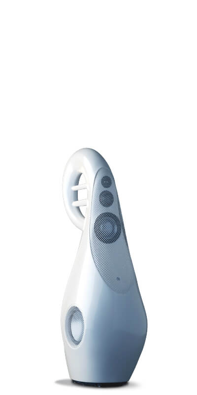
Since spheres are a viable alternative to "boxes" to reduce diffraction, and aren't hard for manufacturers to make (using say injection molds rather than wood), and you can easily insert an offset object inside if there is a standing wave concern, why don't more companies make these? Is it just tradition or marketing people figure most consumers won't like a round speaker enclosure? The pic shows the Demand Better Audio Envy 3 (ok I did take a peak at it as a model for my recent 2-sphere DIY), I think this looks REALLY COOL. But maybe most people don't?
Attachments

Well, that particular loudspeaker looks to me like if would have very low WAF. I woundn’t want them in my living room.
Note that the size of the sphere for the woofer is really too small to be seen as a sphere at the frequencies involved, and the dramatic centre-to-centre of the MT will cause considerable issues.
dve
Note that the size of the sphere for the woofer is really too small to be seen as a sphere at the frequencies involved, and the dramatic centre-to-centre of the MT will cause considerable issues.
dve
Last edited:
The woofer likely produces mid frequencies as well, but yes the low bass won't be affected. There are though all sorts of funky looking designs in higher end products, so many of these that aren't traditional cabinets may also have low WAF. Here my W doesn't want the speakers too far from the wall and not to far from each side of the TV. So placement is certainly not ideal, but it's either that or not have a decent set of speakers and just get a sound bar. What is the percent of audiophile folks with spouses who often are not audiophiles that are constrained by placement, size, shape, etc.? If it's say half, than all of them may be settling for less than they'd otherwise like. My W likes the spheres, adds a touch of difference to the otherwise usual collection of tables, chairs, couches.Well, that articular loudspeaker looks to me like if would have very low WAF. I woundn’t want them in my living room.
Note that the size of the sphere for the woofer is really too small to be seen as a sphere at the frequencies involved, and the dramatic centre-to-centre of the MT will cause considerable issues.
dve
In a 3-way XO over a couple hundred Hz is probably as high as you want ot go, given the disadbantage sof the sphere (at these frequencies), why not something aethetically and more condusive to good bottom.The woofer likely produces mid frequencies as well, but yes the low bass won't be affected
And why not toss the tweeter, there are a growing number of good small FRs that do as wel as some pricey ones. Then you can get rid of the issues with centre-to-centre.
If you have to have a tweeter why not something like the Waveform which uses the egg to good effect.
I envision something like an Alpair 5.2/3 in a 3D printed B&W/Eclipse inspired midTL, with a bass module that gracefully hold the “tear-drop”. XO 300-350 Hz.
dave

I have to say these look pretty weird aesthetically, like an egg was just nailed onto something you sit on with a cushion on top (that just happens to have a couple woofers in it 🙂. The WAF may be very low here? The vast majority of manufacturers haven't tossed the tweeter yet, so FRs don't seem to have made many inroads in higher-end products.In a 3-way XO over a couple hundred Hz is probably as high as you want ot go, given the disadbantage sof the sphere (at these frequencies), why not something aethetically and more condusive to good bottom.
And why not toss the tweeter, there are a growing number of good small FRs that do as wel as some pricey ones. Then you can get rid of the issues with centre-to-centre.
If you have to have a tweeter why not something like the Waveform which uses the egg to good effect.
View attachment 1070069
I envision something like an Alpair 5.2/3 in a 3D printed B&W/Eclipse inspired midTL, with a bass module that gracefully hold the “tear-drop”. XO 300-350 Hz.
dave
I agree that the bass enclosure integration could be better aesthetically. I like the way this was done better in the B&W801. I don’t like their current ones.
You could always do it like Vivid, 4 TLs in these:
dave
You could always do it like Vivid, 4 TLs in these:
dave
I think you don't know how the LX Mini looks like.... the sphere is positioned on top of the cylinder. But of course since you are not using open baffle, you can cross at a much lower frequency... Maybe more accurately it will look closer to a Pluto with a sphere at the end.Cylinders with end mounted drivers don't well in Olsen's charts...
https://www.linkwitzlab.com/Pluto/Pluto-2.1.htm
From their site "...curved surfaces and smooth lines produce a cleaner, more transparent and more honest sound than conventional flat planes and angles. A true four-way system, the G1 Spirit uses five separate drivers to bring you the most seamless, transparent sound you’ve ever experienced, revealing your favourite music in more detail than you ever imagined possible." Looks like a convenient carry handle too! Big 3" vc on the mid-bass which I like (and used a mid bass driver with a 3"er in my recent 2-sphere design - altho I'm sure this driver costs a lot more).I agree that the bass enclosure integration could be better aesthetically. I like the way this was done better in the B&W801. I don’t like their current ones.
You could always do it like Vivid, 4 TLs in these:
dave
One of the things they say here about the transparent sound, that's what I have experienced with low diffraction designs - the openness and sound stage - that I am not sure you can really measure it, but you know it when you hear it.
Now you want to see some truly unique speakers, the Copras from a guy in Odessa Ukraine. He says spent 10 years designing these and the articulated spheres can be positioned how you like. Truly cool and innovative. These are truly a statement in art as well as sound. I hope he is ok still with what's going on over there. https://copra.ua/enI think you don't know how the LX Mini looks like.... the sphere is positioned on top of the cylinder. But of course since you are not using open baffle, you can cross at a much lower frequency... Maybe more accurately it will look closer to a Pluto with a sphere at the end.
https://www.linkwitzlab.com/Pluto/Pluto-2.1.htm
Attachments
I was thinking abit more of the sphere sitting on top of the cylinder. There is quite a lot of engineering going on at Linkwitz stuff. The cylinder case is just a PVC pipe.. not 18mm birch ply. The reason they could get away with such a thin material is because cylinder are pressure vessels. So they don't have to very thick. If you wanted more style can always get your favourite decorative vase.... 😁Now you want to see some truly unique speakers, the Copras from a guy in Odessa Ukraine. He says spent 10 years designing these and the articulated spheres can be positioned how you like. Truly cool and innovative. These are truly a statement in art as well as sound. I hope he is ok still with what's going on over there. https://copra.ua/en
You can read a review that also contains more info about the Envy 3 here: https://www.monoandstereo.com/2014/07/demanding-better-audio-envy-3.htmlWell, that particular loudspeaker looks to me like if would have very low WAF. I woundn’t want them in my living room.
Note that the size of the sphere for the woofer is really too small to be seen as a sphere at the frequencies involved, and the dramatic centre-to-centre of the MT will cause considerable issues.
dve
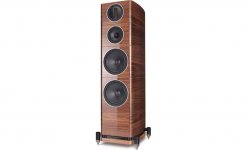
It uses an 8 inch woofer in a 12" dia. polycarb sphere, and the enclosure volume should be fine for that size given it's a sealed system, not ported. I have used a 7" Dayton RS series in a different DIY using an 11" sphere (about 1/3 cu. ft. volume) and that's about what the woofer requires in a sealed system. The center to center on the MT maybe about 9 inches, depends on how far you choose to sit from them. There are many hi-end designs that spread out their drivers in a tower configuration where the MTs are not super close, see the Whaferdale Elysian-4 attached. The MTs look about 7-8" C-to-C. These bad boys run about $5,000 but are not a low diffraction design although have rounded edges.
Attachments
How to build a spherical speaker? Drill lots of holes in an Ikea bowl and mount 1" Aurasound drivers. To get the optimal impulse response from each driver I mounted a segment of car heater hose stuffed with acoustic foam to each one to terminate the back wave. Results? So these drivers individually have a very flat frequency response. Grouped around the sphere together there is cancelation of the upper frequencies due to the proximity of the drivers, so that the response rolls off a lot. So high frequency boost is required to get a flat response again. The other thing I learned was that when you punch that many holes in a spherical shell it gets a bit flexible. So this resulted in a lot of sound coming out of the back of this bowl. Weird as all these are sealed on the back. So the cabinet is flexing. So I expect if I filled the bowl with wax or expanding foam or something to stiffen it and kill the resonance that would help. I stuffed some foam in there and it helped some. I'm currently thinking of pulling out the drivers and using the 3D printer to make geodesic dome segments to mount the drivers in. I may try to sell these rather than destroy them if anyone is interested. If I could recover the cost of the drivers I could just buy more for the next project.


This is pretty amazing
so I might be the only 4-sphere diy guy but this has to be the most drivers ever 🙂
Question how is base ? Or needs a sub
And why not less holes and say 2 in or 3 in drivers ?
so I might be the only 4-sphere diy guy but this has to be the most drivers ever 🙂
Question how is base ? Or needs a sub
And why not less holes and say 2 in or 3 in drivers ?
A thread for you Mr Fisher https://www.diyaudio.com/community/threads/why-is-audio-base-misspelled-as-bass.388549/
dave
dave
- Home
- Loudspeakers
- Multi-Way
- How to build a spherical speaker?