Thanks. I like working with metal, so I've accumulated a few machines. Probably much like you and wood.
Valery,
Just what we need to be able to turn on our sound system before we get home so the amplifier is all warmed up. we can play sounds for the dog when we are at work! 🙄
Just what we need to be able to turn on our sound system before we get home so the amplifier is all warmed up. we can play sounds for the dog when we are at work! 🙄
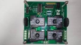
I2C relay control for dual supplies works perfectly first try!😀
Real high-tech 😎
Next century protection!😉I2C relay control for dual supplies works perfectly first try!😀
Excellent Jeff. Does the new relay board happen to have the same footprint / mounting as the main control board? A stacked module where the i2C headers line up would be space saving.
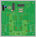
The main control board matches Ostripper's modular supply board. I've got to decide on a standard footprint yet. So far I've been making modules fit the build I happen to be working on at the time.
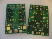
VZDA Compact supply Mk2 boards have arrived from PCBWay. Thanks Jeff! Going to have to hit you up for the firmware for these - you mentioned the device address will need to be changed along with the selection jumper pads to allow for a dual supply?
Next generation power supply will be in effect when Mouser delivers.
Actually initial tests with the Tubsumo will be with a standard cap filter supply then eventually Jeff's protection system will be incorporated when prototyping the enclosure layout.
Next generation power supply will be in effect when Mouser delivers.
Actually initial tests with the Tubsumo will be with a standard cap filter supply then eventually Jeff's protection system will be incorporated when prototyping the enclosure layout.
Attachments
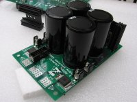
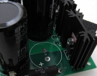
Almost there as far as PCB assembly is concerned. As usual I am obsessing over connectors. Always looking for the best professional wire to board connection where possible, preferably pluggable and lockable/polarized for small signal stuff.
The control modules will be linked by IDC ribbon connectors where possible and the relay board will have Phoenix pluggable terminal blocks, the orientation of which is undecided yet.
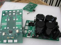
Jeff - The supply boards are lovely, I guess I backed myself into a corner in some areas: the 2512 CRC resistors can be expensive so for this trial I have used 5W 2R2 wirewounds which were salvaged from the parts box. Your original idea of a pair of TH resistors is better and certainly more economical, but one could be on the underside offset to the top one if you get me.
Capacitors with 63VDC rating and 30mm dia can be difficult but EPCOS B41231 series are ideal here.
The discharge indicator LED's are in a very tight spot between the first caps and heatsinks, in fact 3mm LED's are needed here or they should be moved to the outer edge, parallel to their current position (4th pic). As it happens I may run the LED's from headers/leads to the front nicely showing the amp power down.
The higher the diode voltage drop the better with these LED's really?
Can space be made on both the main control and relay board for connection together using 8P IDC ribbon connectors? The control board can fit an IDC board header with a bit of hacking to clear the pins of U1 but unfortunately there is no clearance on the relay board between U1 and U3. It would mean increasing the board dimension by approx 3 - 5mm.
I had something else, but have forgot... anyway these are mere suggestions Jeff, everything is superb and I'm more than happy and anxious to get all this pro electronics working.
The control modules will be linked by IDC ribbon connectors where possible and the relay board will have Phoenix pluggable terminal blocks, the orientation of which is undecided yet.
Jeff - The supply boards are lovely, I guess I backed myself into a corner in some areas: the 2512 CRC resistors can be expensive so for this trial I have used 5W 2R2 wirewounds which were salvaged from the parts box. Your original idea of a pair of TH resistors is better and certainly more economical, but one could be on the underside offset to the top one if you get me.
Capacitors with 63VDC rating and 30mm dia can be difficult but EPCOS B41231 series are ideal here.
The discharge indicator LED's are in a very tight spot between the first caps and heatsinks, in fact 3mm LED's are needed here or they should be moved to the outer edge, parallel to their current position (4th pic). As it happens I may run the LED's from headers/leads to the front nicely showing the amp power down.
The higher the diode voltage drop the better with these LED's really?
Can space be made on both the main control and relay board for connection together using 8P IDC ribbon connectors? The control board can fit an IDC board header with a bit of hacking to clear the pins of U1 but unfortunately there is no clearance on the relay board between U1 and U3. It would mean increasing the board dimension by approx 3 - 5mm.
I had something else, but have forgot... anyway these are mere suggestions Jeff, everything is superb and I'm more than happy and anxious to get all this pro electronics working.
Attachments

Last edited:
Check out Newark/Farnell for the 2512 resistors. They have stock reduction blowouts regularly and their house brand Multicomp resistors are inexpensive and good quality.
Nichicon has 30mm caps in 80V.
It looks like the model I drew for the heat sinks is a little small. Anything is fine for leds. I'm not sure if you would want them showing on the front panel of your amp. They stay on for quite a while after power down because your rail feeds will shut down when you turn your amp off. The only thing draining the supply will be your bleed off resistors.
That relay board is meant to plug right into the control board with right angle connectors. It was layed out to stack on Ostripper's modular supply. I'm going to design a series of I2C controlled relay modules for connecting with a ribbon cable, when time permits.
This is a great project. thank you for the effort and time for such a project. I am very interested in this project, if you could send me some information and software necessary to thank me immensely.
Respect.
Respect.
I2C ?
Instead of using the digital outputs on the arduino / 328 , we use clock/data (SCA/SCL) and then wire.xxx commands (plus the external device address)
to access remote boards - devices ?
So , any amp could actually have both rail and speaker MOSFETS remotely
controlled by a central micro.
Wow , this is quite jump forward ... it would be just as easy to protect
a 5 channel setup as a stereo one - as many "slaves" as you can add !!
I also read about all the other I2C devices (CN75 temperature sensor).
It looks like you could replace any of the analog sensors -
I2C hall current sensors - I read about the allegro ASC710 - internal
copper bus , hall sensor , A/D , and I2C interface.
This would indeed bloat the firmware , (how much current and for how long)
-would have to be scripted in.
But something like this might be the "all the way" endgame.
OS
Yes, we've got a lot of flexibility now - instead of just reacting on overtemp alert, we can actually track the temperature and control the optional fans (for professional applications), have as many current sensors as we need and as many SS relays as we need - and all those things are connected via the common bus. No need to endlessly increase the number of GPIO pins any more.
Allegro current sensors are cool. You can set the limit you want to watch and it will raise an alert in less than 2 uS as soon as the limit is broken.
I also know how to make an I2C interface (I2C bridge) out of an 8-pin PIC12F1840 chip. They cost nothing, very standard, and can be used as many as required. As an option for interfacing some sensors with no I2C interface (like DC offset one).
The sky is not the limit 😛
- Home
- Amplifiers
- Solid State
- How to build a 21st century protection board