Allegro MicroSystems - ACS764 Fully Integrated, Hall-Effect Based Current Sensor IC With I²C Digital Output and Low-Resistance Current Conductor
I posted the analog one before , the ACS764 is the digital "beast".
Many use this chip to poll battery charging currents for solar.
I've seen the code they use to identify Lithium battery failure.
But , all this polling using the same bus as the relays (and other sensors)
might overwhelm a little atmega. There is also much more example code
for using an analog hall sensor connected to the arduino A/D.
ACS758 could be used for both rails and amp output.
What is cool , they (robotic and solar hobbyist's) have "profiled" currents
to control the appropriate relays. No reason why any amp fault could not
also be profiled by its current use.
OS
That depends on how quickly you want to do your trips.
Since that sensor only supports i2c rate up to 400kHz that will be a big restriction on how many amplifiers you can put on one bus. If you're sensing four parameters (3 currents and one voltage through another i2c dac for example) per amplifier channel then you will probably reach around the 150us cycle rate, so a four channel amplifier would be around the 600 us mark already.
Of course, if you adopted something more powerful like the mbed platform, where you can easily get uC's with 3 or more i2c you could expand quite a bit more. But you'd have to weigh it against using a small local controller to perform the fast trips and having the main controller mostly supervising.
I haven't made the full plunge to I2C control yet. The speaker relays are still connected to a digital interupt pin. We're nowhere close to bogging down the ATmega from software yet, but the I2C bus runs at 100 kHz, and each action is 17 or 18 bits, so if too many devices are added, eventually things will slow down.
The DC protection still has it's redundant self contained shut down and the first I2C command is to shut down the power rails in the supply.
The DC protection still has it's redundant self contained shut down and the first I2C command is to shut down the power rails in the supply.
Yes, the "beauty" of the solution - speakers will be saved via the hardware "channel" even if the controller fails - this feature was part of the design from the very beginning.
I should probably do a more "polished" version of the control board soon. I used a 12 pin connector for the I2C bus connection. I figured out after, it's almost impossible to get a nice IDC connector and matching keyed header in 12 pin. I should probably be making the I2C bus separate and make it easy to connect a ground shield. A separate shielded power cable containing ground, 5V and 12V to run along side it would be nice. I'm going to check out IDC round cable options for these. The flat ribbon cable is easy to assemble, but doesn't turn well in tight places.
Yes, the "beauty" of the solution - speakers will be saved via the hardware "channel" even if the controller fails - this feature was part of the design from the very beginning.
Yes , I would never want DC to be (fully) reliant on a stupid 'puter.
DC is what I have tripped several times.
Current once (a screwdriver) , thermal just for test.
Still have all my speakers.
OS
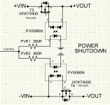
i got some mosfet driver PVI5080N on hand.. is the attach circuit enough to power my subwoofer of 500 watts rms at +/-78vdc rail.
any mistake on the circuit?
IXFK73N30 300V 73A 45mΩ
thanks
Dacz
any mistake on the circuit?
IXFK73N30 300V 73A 45mΩ
thanks
Dacz
Attachments
Last edited:
i got some mosfet driver PVI5080N on hand.. is the attach circuit enough to power my subwoofer of 500 watts rms at +/-78vdc rail.
any mistake on the circuit?
IXFK73N30 300V 73A 45mΩ
thanks
Dacz
Your mosfet drivers are connected to the mosfets backwards. Pin 5 should go to the gate, pin 8 to the source.
It doesn't look like the driver contains fast off circuitry, so it might be a little slow reacting on shutdown.
thank you for the correction.. anyway i found out that these driver are for logic level mosfet (5V).
The PVI5080N is designed to match the gate
characteristics of logic level MOSFETS as illustrated in
this article.
thanks
The PVI5080N is designed to match the gate
characteristics of logic level MOSFETS as illustrated in
this article.
thanks
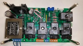
I almost have the next generation of 21st Century Protection ready for testing, but I noticed an error on the control/relay board.😡 New boards are on order.
The new control board will still connect to the previous design speaker relay/DC detection. It can also be connected to a pair of emitter resistors for current sensing, but can also connect with I2C current sensors. Thermal sensing will be strictly I2C. Next step will be integrating it with a singleboard computer for web interface and datalogging. A LCD screen can easily be interface via I2C as well if so desired.
I've designed a 2" x 2.1" SMT speaker relay/DC protection board to go with it as well as a standalone I2C temp sensor board.
Attachments

Excellent work... JW, I am taking note of your SMD layouts - and real world
device sizes (1206R's , sot-23-3,soic-8).
OS
device sizes (1206R's , sot-23-3,soic-8).
OS
Anything down to .050" pin centers is easy to solder. .035" centers are a little more tricky, but is easy with a little practice.
Custom pattern with a little more exposed copper at the end of the pins makes soldering easier too. More room to get the iron to the trace helps for newbies.
Custom pattern with a little more exposed copper at the end of the pins makes soldering easier too. More room to get the iron to the trace helps for newbies.
Last edited:
Yeah - great job! I'm thinking about selecting some easily available I2C LCD module that we can use as a standard option for indication - showing all the detailed statuses with words, countdown in seconds during startup, etc.
Some 2x16 (2-lines character display) would be sufficient, I believe.
Some 2x16 (2-lines character display) would be sufficient, I believe.
Most displays small displays are standardized. I use these. https://ca.mouser.com/Search/Produc...tualkey66010000virtualkey763-0216K1Z-FSPG-GBW There are lots of options for colours for lettering and backlighting.
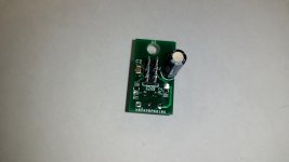
I convert them to I2C on a small daughter-board with a MCP23008 expander.
Here's a daughter-board for a 4 x 20 display that I'm using for another project. It's virtually the same board with screw holes moved.
I convert them to I2C on a small daughter-board with a MCP23008 expander.
Here's a daughter-board for a 4 x 20 display that I'm using for another project. It's virtually the same board with screw holes moved.
Attachments

Hi,
I used this one for all my projects from Mouser Part #:763-0420D3ZNSWBBW- V3 . It is I2C, RS-232, SPI and the RS-232 it is TTL output. It is used 3 lines only for communication. +5,GND and the data line. It is a little pricey but also it is easy to program. It come in 2 & 4 lines display.
I used this one for all my projects from Mouser Part #:763-0420D3ZNSWBBW- V3 . It is I2C, RS-232, SPI and the RS-232 it is TTL output. It is used 3 lines only for communication. +5,GND and the data line. It is a little pricey but also it is easy to program. It come in 2 & 4 lines display.
Hi,
I used this one for all my projects from Mouser Part #:763-0420D3ZNSWBBW- V3 . It is I2C, RS-232, SPI and the RS-232 it is TTL output. It is used 3 lines only for communication. +5,GND and the data line. It is a little pricey but also it is easy to program. It come in 2 & 4 lines display.
Those do look nice to work with. Do you know if they will work with the standard Arduino libraries, or is the communication language different?
Hi,
No, because I used the Zbasic and Basic Nano micros for my projects. I just stated to learn programming the Arduino Uno. I do not know if you can use the Arduino LCD library. For the Zbasic and the Basic Nano I used my own routine that I built myself for sent messages to the dislay.
No, because I used the Zbasic and Basic Nano micros for my projects. I just stated to learn programming the Arduino Uno. I do not know if you can use the Arduino LCD library. For the Zbasic and the Basic Nano I used my own routine that I built myself for sent messages to the dislay.
I have a feeling the language is different. Otherwise more people would be using them.
The standard Arduino I2C libraries run pretty slow and hog a lot of processing power when writing to an I2C LCD. I came across a library with much better speed and lower resource use.
The standard Arduino I2C libraries run pretty slow and hog a lot of processing power when writing to an I2C LCD. I came across a library with much better speed and lower resource use.
Hi,
If you know how to send an string of 20 character that is the only thing you need to do. Just look at the data sheet and will see that to communicate with the display it is completely easy.
If you know how to send an string of 20 character that is the only thing you need to do. Just look at the data sheet and will see that to communicate with the display it is completely easy.
With a standard Arduino library you would type
lcd.setCursor(0, 0); // first row, first character
lcd.print("whatever you want it to say");
Is that the same sort of command structure?
lcd.setCursor(0, 0); // first row, first character
lcd.print("whatever you want it to say");
Is that the same sort of command structure?
- Home
- Amplifiers
- Solid State
- How to build a 21st century protection board