Finally had the time to get the first protection set working. The only thing I can't figure is why I waited so long to implement this solution. Huge thanks to jwilhelm for all the help and to vzaichenko for the ideas. Now to collect the parts and do the other 5 sets.
Finally had the time to get the first protection set working. The only thing I can't figure is why I waited so long to implement this solution. Huge thanks to jwilhelm for all the help and to vzaichenko for the ideas. Now to collect the parts and do the other 5 sets.
Hi Evan,
Good to hear you like it! Welcome to the 21-st Century Club 😛
Cheers,
Valery
Finally had the time to get the first protection set working. The only thing I can't figure is why I waited so long to implement this solution. Huge thanks to jwilhelm for all the help and to vzaichenko for the ideas. Now to collect the parts and do the other 5 sets.
Sounds great can you show some pictures please?
☺
Finally had the time to get the first protection set working. The only thing I can't figure is why I waited so long to implement this solution. Huge thanks to jwilhelm for all the help and to vzaichenko for the ideas. Now to collect the parts and do the other 5 sets.
Did the speaker relay work out okay? I've never built that version yet. The protection system does get a little expensive, but it's money well spent to protect those monster speakers you are running.
The speaker relays seem to be doing their job. the surface mount parts were easy to solder. I put the first set on a tubsumo +- 70 volt rails. With a test speaker hooked up I turned off power to the whole system at once. This would usually have ruined my mids and tweeters as the preamp turns off a lot faster then the power amps. There was only the tiniest click from the speaker. I have not tried disconnecting at full power. They will probably have more work to do disconnecting the five pair slewmonsters.
I'm off to work today. Pics of the preliminary set up later on.
Evan
I'm off to work today. Pics of the preliminary set up later on.
Evan
I made a delivery of a dining table I put together for a customer. My profit is mostly in the final payment I get on delivery. To be honest I don't even know who is playing in the Superbowl.
E
E
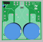
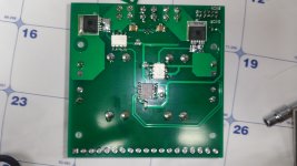
I've got a new evolution of the supply with rail shutdowns in the works. It's I2C controlled for easy connection and has an output header on board for feeding the remote speaker relay. I didn't like the fact that we were feeding the speaker relay from a huge cap bank, so I added onboard self resetting fuses to the header feeds. It also has onboard rail fuses for the main outputs (at the supply where they belong!).😀
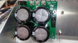
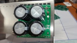
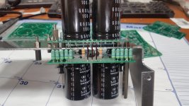
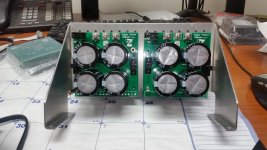
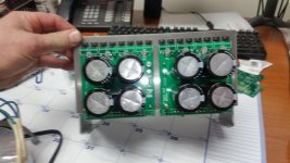
This one's designed for mono-block amplifiers, but is compact enough to fit two in a single chassis with a little ingenuity. The supply consists of two boards, joined together by resistors to form a CRC supply. They should stand on end back to back nicely.
This one's designed for mono-block amplifiers, but is compact enough to fit two in a single chassis with a little ingenuity. The supply consists of two boards, joined together by resistors to form a CRC supply. They should stand on end back to back nicely.
Attachments


Looks nice. Rail disconnects seem like a good idea. Room for lots of smaller resistors for the r in the crc also seems nice and less costly.
100V caps are getting harder to find in snap in leads. I had to come up with a way to get lots of them in a small area for my latest amp build. That's what inspired these.
Those pads at the bottom aren't all CRC resistors. There's three ground jumpers and two bleeder resistors in there too. There's room for seven 3W CRC resistors per rail, which should be plenty for a single channel.
Those pads at the bottom aren't all CRC resistors. There's three ground jumpers and two bleeder resistors in there too. There's room for seven 3W CRC resistors per rail, which should be plenty for a single channel.
The protection board saved my butt the other day. I put the lid on the amplifier while it was switched on. The lid slipped and shorted the speaker output.
There was no drama. The channel was shut down and the mosfetrelay disconnected the amp without a noise from the speaker. After reset the amplifier was working as if nothing had happened. 🙂
There was no drama. The channel was shut down and the mosfetrelay disconnected the amp without a noise from the speaker. After reset the amplifier was working as if nothing had happened. 🙂
The protection board saved my butt the other day. I put the lid on the amplifier while it was switched on. The lid slipped and shorted the speaker output.
There was no drama. The channel was shut down and the mosfetrelay disconnected the amp without a noise from the speaker. After reset the amplifier was working as if nothing had happened. 🙂
Cool
 Thanks for sharing 😉
The protection board saved my butt the other day. I put the lid on the amplifier while it was switched on. The lid slipped and shorted the speaker output.
There was no drama. The channel was shut down and the mosfetrelay disconnected the amp without a noise from the speaker. After reset the amplifier was working as if nothing had happened. 🙂
You do your own live testing.😀 I have a stupid cat that does mine.
The speaker relays are a little expensive to build, but money well spent!
JW,
that is the supply just for the protection circuit? Looks nicely designed just didn't think you would need something like that to run the speaker protection boards.
that is the supply just for the protection circuit? Looks nicely designed just didn't think you would need something like that to run the speaker protection boards.
That's a main power supply for an amplifier with rail shutoffs controlled by the protection system. If there's a problem detected in the amplifier, rail power is shut off along with everything else, so there's no supply caps bleeding off into a damaged amplifier.
Thanks JW that makes more sense than that you would need a cap bank like that just to power the protection. Is that enough to drive the Slewmaster with five pairs?

- Home
- Amplifiers
- Solid State
- How to build a 21st century protection board