I've been trying to evolve the design to make it easier for people to take a newly built amplifier and put it into safe service without a lot of extra effort. It's working out nicely so far. As is now it can control multiple power supplies (pending successful testing of the I2C relay board). Speaker protection is monitored over a ribbon cable and many can be daisy chained together. At present only two channels of overcurrent and thermal protection are supported, but that will cover 99% of builds. The protection board itself and the main relay boards are designed on the same footprint as Ostripper's modular supply so they are neatly stack-able. Having a control transformer on board would be really slick, but this will limit the mounting locations and parts availability.
During a conversation in PM with EvanC this morning another cool idea came to mind. A delayed 12V trigger output might be handy. He has half a dozen monsters he needs to fire up to get his system running. It would be slick to use the 12V trigger signal into the control board, then have it send out another 12V signal to start the next amp a second later. That way all amps could be started from one trigger event or power button, without browning out the neighbourhood.
Yes, delayed trigger output signal is a good idea for comprehensive installations, like Evan's 😉
Rail fuses are still in place for normal slow overload protection.
The beauty of this being a complete integrated protection system is there are all the other protections to fall back on. If you were to have 1.9V at the detection input for a sustained period, there's a good chance you will also have DC at the speaker connection which would shut the amp down. If not there is also thermal monitoring in place that will shut things down.
that sounds good.Exactly - overcurrent protection shuts down the amp on fast high current rises, thermal protection handles the lower but longer overloads, and in many cases these troubles are accompanied with DC offset - so, in these cases, based on experience, DC protection trips earlier than the other ones 😉
How is SOAR protection achieved?
Do you mean a sort of prolonged clipping? If this is the case - a well-designed amplifier survives clipping during some time, but normally starts heating up. In our case - until over-temperature sensor triggers the board to shut down the amp.
How is SOAR protection achieved?
I feel real-time SOAR protection needs to be designed into the amplifier.
This type of 'add on' has no reference as to what a given amplifier design has available for safe operating area, therefore it would either have to make broad conservative 'assumptions' or be explicitly programmed based on an individual builds capabilities.
The design is pretty comprehensive already and will catch most negligent / ham-fisted / whoops / 'hold my beer while I try this' type scenarios. The rest requires some understanding of an individual builds' capabilities and possible restraint on the user's part.
I think it's easier to add a couple extra output devices than worry too much about running to the edge of SOAR. We tend to over-do everything else in the DIY world, why not output devices?
I think it's easier to add a couple extra output devices than worry too much about running to the edge of SOAR. We tend to over-do everything else in the DIY world, why not output devices?
Yes, I like the approach to OPS design, so that if you accidentally shorten the output with a small screwdriver - screwdriver melts and thus the problem disappears 😀 In case of a big screwdriver - protection shuts down the amp 😎
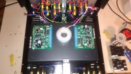
I'm rebuilding my amp with the protection boards, it's going to be tight.
I didn't want to hide the trannies but I can't see any better solutions that leaves enough space in the back to replace the IPS and adjust bias.
I didn't want to hide the trannies but I can't see any better solutions that leaves enough space in the back to replace the IPS and adjust bias.
Attachments

I'm rebuilding my amp with the protection boards, it's going to be tight.
I didn't want to hide the trannies but I can't see any better solutions that leaves enough space in the back to replace the IPS and adjust bias.
Hi yngvejos,
In fact, using two control boards makes sense if you have separate compartments for the amps. In your case of dual mono, you can easily use one board for both channels - it will monitor them independently, so that they will not influence each other through the control board.
Cheers,
Valery
I feel real-time SOAR protection needs to be designed into the amplifier.
This type of 'add on' has no reference as to what a given amplifier design has available for safe operating area, therefore it would either have to make broad conservative 'assumptions' or be explicitly programmed based on an individual builds capabilities.
The design is pretty comprehensive already and will catch most negligent / ham-fisted / whoops / 'hold my beer while I try this' type scenarios. The rest requires some understanding of an individual builds' capabilities and possible restraint on the user's part.
The SOAR diagram is part of every manufacturer's data sheet for power BJTs.
However, these data are for a constant junction temperature and one has to derate according to actual junction temp.
Agreed for DIY purposes this is a minor issue but when it is about reliability
it becomes a major issue. After all no life performance can afford broken amps.
I have seen a commercial amp which has a DAC/µP based board and controls a sort of soft clipper, it takes the case temperatures also.
Won't one board mean Connecting the psu grounds together? Now they are floating indepentently.
Anyway, I like the idea to control the startup of the two transformers indepentently so that I can put a delay on one of them to reduce the load on the mains circuit breaker. Also it's nice with one error indicator per channel. 😉
Anyway, I like the idea to control the startup of the two transformers indepentently so that I can put a delay on one of them to reduce the load on the mains circuit breaker. Also it's nice with one error indicator per channel. 😉
Hi yngvejos,
In fact, using two control boards makes sense if you have separate compartments for the amps. In your case of dual mono, you can easily use one board for both channels - it will monitor them independently, so that they will not influence each other through the control board.
Cheers,
Valery
Using one control board will connect the grounds of both amplifiers together. Won't that leave them more susceptible to ground loops?
I start two transformers with two soft starts. That allows each transformer to be fed with a close rated mains fuse.
eg two 300VA 230Vac transformers with 80r of current limiting resistance for each transformer. The two fuses would be T1.25A
There is absolutely no problem starting both transformer from the same soft start and using a 2pole relay to short out the two limiting resistors after the 150ms delay.
There is no massive draw on the mains supply.
USA and Canada Builders will need T2.5A fuses and 40r resistors for their 115Vac soft starts.
Again the peak start up draw of the two transformers is not high. The current limiting resistors ensure that.
Last edited:
Using one control board will connect the grounds of both amplifiers together. Won't that leave them more susceptible to ground loops?
Well, we can opto-decouple all the sensor signals for that purpose easily 😉
There will be no reason of having two controllers then at all.
Well, we can opto-decouple all the sensor signals for that purpose easily 😉
There will be no reason of having two controllers then at all.
This is why my latest speaker protection is opto isolated. The boards he is using had the on board stereo speaker relays.
I start two transformers with two soft starts. That allows each transformer to be fed with a close rated mains fuse.
eg two 300VA 230Vac transformers with 80r of current limiting resistance for each transformer. The two fuses would be T1.25A
There is absolutely no problem starting both transformer from the same soft start and using a 2pole relay to short out the two limiting resistors after the 150ms delay.
There is no massive draw on the mains supply.
Good approach. But no problem to start the transformers one by one for the control board like ours.
I start two transformers with two soft starts. That allows each transformer to be fed with a close rated mains fuse.
eg two 300VA 230Vac transformers with 80r of current limiting resistance for each transformer. The two fuses would be T1.25A
There is absolutely no problem starting both transformer from the same soft start and using a 2pole relay to short out the two limiting resistors after the 150ms delay.
There is no massive draw on the mains supply.
USA and Canada Builders will need T2.5A fuses and 40r resistors for their 115Vac soft starts.
Again the peak start up draw of the two transformers is not high. The current limiting resistors ensure that.
The latest design actually has provisions to control two sets of relays independently. Each transformer can then be independently fused at a lower fuse rating.
This is why my latest speaker protection is opto isolated. The boards he is using had the on board stereo speaker relays.
Yes, opto isolation is great - it also protects the control board in case of big troubles with the amp (so that the control is always there).
I had a bad hum in my first Slewmaster build that came from my control board being grounded through the 12V regulator heat sink. That's what originally gave me the idea to isolate the speaker protection.
I'm trying to get the multicolored led to work. When I put the led in the arduino uno board cathode to gnd, and the anodes to D4 and D12 it works fine.
When I put it in the amp control board with Cathode to led-, anode to led + and the other anode to D12, the part of the led connected to D4 is lit at all times (even if I take the original script and change "const int PowerLED = 4; // LED Bright LOW" to "const int PowerLED = 12; // LED Bright LOW)". And I get no output on D12.
How can I get output on D12?
- Home
- Amplifiers
- Solid State
- How to build a 21st century protection board