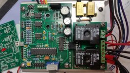
My next evolution of boards have arrived. Lots to test!😎
Excellent evolution!

By the way, I had an interesting issue - using an old big board - the one with standby transformer right on it - in my new amp, in the compartment.
A few times during the listening, or even with no signal, I had the amp shut down, indicating overcurrent conditions. Quick research has shown - there was no overcurrent in fact - I have even removed HCPL opto chip - it still happened. It happens only within the compartment - never happened on a test bench.
The problem was - due to the long traces and the filtering cap (10nF) location, being too far from the microcontroller, some quick parasitic impulse made the controller think there was an overcurrent signal from the sensor.
Solution: the value of the resistor going from the corresponding controller input to +5V is decreased from 4.7K to 2,2K and 100nF capacitor is added from that input to the ground very close to ATMega chip. No false shutdowns since then.
Cheers,
Valery
Design tip for anyone doing their own PCB layouts.
The false triggering on overcurrent is interesting. I had a look at the layout. I think it has more to do with the placement of the filter cap than the length of the traces. Current flows between R42 and the Arduino pin, but has a separate trace coming from R42 off to a cap 4" away. This is something I see autorouters try to do every time I use them.
Most of my design experience has been in automotive environment, which is pretty much the nastiest possible environment to work with. I had to figure out filtering and decoupling quickly, because there was so much noise on every circuit of a vehicle, nothing would operate properly.
For a filtering cap to be most effective, it should be right in the path of current flow to whatever it is filtering. Current shouldn't have the option of flowing past it, without touching it. Electricity, like anything else, will take the easiest route, so that route should be right to the cap. This is why I keep suggesting it has a separate in and out path whenever possible. Using a common in/out trace causes double the current flow in that trace, causing twice the resistance = less effective filtering.
Jeff that dc protect board looks very nice.
I am going to have to get off my but and put together a solution that works for my situation.
If you don't mind me asking the first of probably many questions...Would this work stand alone? I assume that the j3 pin 3 speaker on connection is held to ground to get things going.
Thanks, E
I am going to have to get off my but and put together a solution that works for my situation.
If you don't mind me asking the first of probably many questions...Would this work stand alone? I assume that the j3 pin 3 speaker on connection is held to ground to get things going.
Thanks, E
It can be modified to work standalone, but the rest of the protection circuits working together with it will stop a lot of collateral damage in the amplifier on failure. Alone it will protect your speakers if an output device shorts, but that won't stop the amp from melting down and stinking your house up. Having it shut the amplifier down is a very nice additional option.
I've bench tested the speaker protection. It works very reliable and triggers at + or - 1.35VDC. I need to do some further testing with AC signal yet, but am having a glitch in the power switch circuit in the new control board I need to sort out before further testing.
I located a broken trace in the power switch circuit on my tester protection board. it looks like PCBWays free 100% board testing is BS. I've got it patched up and did some more testing. The protection board itself works perfectly. Overcurrent protection is activating at 2.0VDC (4.54A with .22 emitter resistors). I was able to trigger power loss detection with a quick disconnect and reconnect of mains supply. Overtemp activated when I jumpered the connectors, proper testing still to come.
I did some more testing of the speaker protection. With 10VAC applied to the speaker input, protection activated at 0.5Hz. With AC signal present, DC offset of 1.3V activated the protection. It needs some real testing in circuit now. I will need to make a resistor selector chart for different rail voltages eventually too.
Next to test is the I2C controlled power relays, but I need to modify some software first. I'm really liking these relay modules. They make wiring much neater.
Attachments
It is great to hear about the project going well☺look to forward to see more results☺I located a broken trace in the power switch circuit on my tester protection board. it looks like PCBWays free 100% board testing is BS. I've got it patched up and did some more testing. The protection board itself works perfectly. Overcurrent protection is activating at 2.0VDC (4.54A with .22 emitter resistors). I was able to trigger power loss detection with a quick disconnect and reconnect of mains supply. Overtemp activated when I jumpered the connectors, proper testing still to come.
I did some more testing of the speaker protection. With 10VAC applied to the speaker input, protection activated at 0.5Hz. With AC signal present, DC offset of 1.3V activated the protection. It needs some real testing in circuit now. I will need to make a resistor selector chart for different rail voltages eventually too.
Next to test is the I2C controlled power relays, but I need to modify some software first. I'm really liking these relay modules. They make wiring much neater.
I presume this is triggering with a DC current....................Overcurrent protection is activating at 2.0VDC (4.54A with .22 emitter resistors). ................
Is there a way to pass a transient current say 10ms of double that value?
Could it pass a 1us current of triple that value?
It's these "safe" transient currents that make up the music.
A protection system should allow all valid audio signals to pass to all valid audio loads.
I presume this is triggering with a DC current.
Is there a way to pass a transient current say 10ms of double that value?
Could it pass a 1us current of triple that value?
It's these "safe" transient currents that make up the music.
A protection system should allow all valid audio signals to pass to all valid audio loads.
Overcurrent sensing is measuring 1 pair, so in a 5 pair Slewmonster for example it would activate at around 20A. Reaction speed can be altered by changing R18 if required, but this circuit is pretty much a copy and paste of previous designs. I've never experienced a false trigger, but when required, the amplifier is shut down faster than a rail fuse could blow. My cat has done rigorous short circuit testing for me.
So I am asking have you considered how to set different levels of trigger depending on the duration of the overload?
i.e. a lower level trigger for a long duration current and a higher trigger level for a short duration transient.
Or put it another way, let's pick a current level at which the protection does not trigger, say 18Adc and let that pass through to an abnormal load. Would the mains fuse eventually blow after the amp output stage has blown up?
DC and long term overload/trigger levels need to be low enough such that no damage ensues as the heatsinks and the devices heat up to above acceptable temperatures.
A simple RC filter before the detect circuit may give some version of this discrimination without blocking a valid output signal into a valid output load.
Last edited:
No I haven't. This is a single trigger point design triggering an optoisolator that is set up to act as a fast blow fuse. Rail fuses are still in place for normal protection. As is it works very well. My only concern is it won't catch a current hogging pair if the amplifier cooling isn't correct.
Eventually I would like to experiment with a current sensing AD converter that will allow multiple current sensing schemes in software. I would like to do this on a I2C bus, but I haven't checked into how this will effect the sampling rate yet.
I've also done some testing with rail shutdown via mosfets with very good results, so an oversized power supply won't dump into a damaged amplifier. This may help reduce the bad smell when a badly abused amplifier finally does expire.
Last edited:
So I am asking have you considered how to set different levels of trigger depending on the duration of the overload?
i.e. a lower level trigger for a long duration current and a higher trigger level for a short duration transient.
Or put it another way, let's pick a current level at which the protection does not trigger, say 18Adc and let that pass through to an abnormal load. Would the mains fuse eventually blow after the amp output stage has blown up?
DC and long term overload/trigger levels need to be low enough such that no damage ensues as the heatsinks and the devices heat up to above acceptable temperatures.
A simple RC filter before the detect circuit may give some version of this discrimination without blocking a valid output signal into a valid output load.
We can measure timing with the microcontroller, which is pretty fast, but in order to make the whole thing really robust, we need to carefully define the conditions for triggering and we need - as Jeff has just mentioned - multi-level sensing.
This is a sort of a compromise between the maximum speed and decent intelligence. At the moment it is designed to work at the maximum speed as soon as 2V at 2 x 0.22R resistors is exceeded.
I see that as the problem.At the moment it is designed to work at the maximum speed as soon as 2V at 2 x 0.22R resistors is exceeded.
1.9V at the detector does not initiate protection.
Will the output stage survive with that level of signal across the sensing element for ever, or for an hour, or for a minute?
If one went to answer the phone, or the door, or the spouse calling and did not notice that an incident had occurred (or in my case gone to bed with the system still switched on) would the output stage survive?
I see that as the problem.
1.9V at the detector does not initiate protection.
Will the output stage survive with that level of signal across the sensing element for ever, or for an hour, or for a minute?
If one went to answer the phone, or the door, or the spouse calling and did not notice that an incident had occurred (or in my case gone to bed with the system still switched on) would the output stage survive?
Rail fuses are still in place for normal slow overload protection.
The beauty of this being a complete integrated protection system is there are all the other protections to fall back on. If you were to have 1.9V at the detection input for a sustained period, there's a good chance you will also have DC at the speaker connection which would shut the amp down. If not there is also thermal monitoring in place that will shut things down.
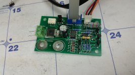
Got my boards up and running today, they seem to work Perfect. I have to figure out how to modify the code for multicolor led before I put them in the amp.
Rail fuses are still in place for normal slow overload protection.
The beauty of this being a complete integrated protection system is there are all the other protections to fall back on. If you were to have 1.9V at the detection input for a sustained period, there's a good chance you will also have DC at the speaker connection which would shut the amp down. If not there is also thermal monitoring in place that will shut things down.
Exactly - overcurrent protection shuts down the amp on fast high current rises, thermal protection handles the lower but longer overloads, and in many cases these troubles are accompanied with DC offset - so, in these cases, based on experience, DC protection trips earlier than the other ones 😉
Got my boards up and running today, they seem to work Perfect. I have to figure out how to modify the code for multicolor led before I put them in the amp.
Let me know what exactly LED you are going to use and what colour will mean what - I can modify the code quickly 😉
Thanks 🙂
Here's the leds. WP59EGW Kingbright | Mouser
My planned colors:
Standby: red
Inrush: red and green at the same time
On: green
Alarms: alternating red and green
Here's the leds. WP59EGW Kingbright | Mouser
My planned colors:
Standby: red
Inrush: red and green at the same time
On: green
Alarms: alternating red and green
I've been trying to evolve the design to make it easier for people to take a newly built amplifier and put it into safe service without a lot of extra effort. It's working out nicely so far. As is now it can control multiple power supplies (pending successful testing of the I2C relay board). Speaker protection is monitored over a ribbon cable and many can be daisy chained together. At present only two channels of overcurrent and thermal protection are supported, but that will cover 99% of builds. The protection board itself and the main relay boards are designed on the same footprint as Ostripper's modular supply so they are neatly stack-able. Having a control transformer on board would be really slick, but this will limit the mounting locations and parts availability.
During a conversation in PM with EvanC this morning another cool idea came to mind. A delayed 12V trigger output might be handy. He has half a dozen monsters he needs to fire up to get his system running. It would be slick to use the 12V trigger signal into the control board, then have it send out another 12V signal to start the next amp a second later. That way all amps could be started from one trigger event or power button, without browning out the neighbourhood.
During a conversation in PM with EvanC this morning another cool idea came to mind. A delayed 12V trigger output might be handy. He has half a dozen monsters he needs to fire up to get his system running. It would be slick to use the 12V trigger signal into the control board, then have it send out another 12V signal to start the next amp a second later. That way all amps could be started from one trigger event or power button, without browning out the neighbourhood.
- Home
- Amplifiers
- Solid State
- How to build a 21st century protection board