Opto-isolation is a better idea. Something like this would work.
http://www.mouser.com/ds/2/205/CPC5902-740833.pdf
I2C AD converters are easy to work with using the Wire library. Just request the number of bits from the AD converter address. It's the same as using an analog in pin.
http://www.mouser.com/ds/2/205/CPC5902-740833.pdf
I2C AD converters are easy to work with using the Wire library. Just request the number of bits from the AD converter address. It's the same as using an analog in pin.
How would that work with a 0-5v analog input? A regular opto-coupler is not linear enough to output the voltage correctly (so I've been told).
Any room on your board to add this device or something similar in size? I would probably socket it just in case in blows.
I might be over thinking this, I simply want to trigger the board off when voltage goes too high. Resolution needs to be decent since the trip point may be from 3v to 3.1v
Any room on your board to add this device or something similar in size? I would probably socket it just in case in blows.
I might be over thinking this, I simply want to trigger the board off when voltage goes too high. Resolution needs to be decent since the trip point may be from 3v to 3.1v
You are overthinking this.
The AD converter would convert the signal from 0-5VDC to a binary value, then you read it digitally over an I2C bus(analog pin 4 & 5). Use the wire library in the arduino IDE.
Wire.requestFrom (AD converter address, number of bits it spits out)
If you are using a 8 bit AD converter it will convert to a number from 0 - 255. The opto-isolator stops anything bad from happening to the microcontroller.
But if you really want to keep it simple, look at the on board overcurrent (bias) sensing circuit Vzaichenko designed for this. It uses a voltage divider as you want to do. Tune it so the threshold voltage you want to trigger at causes current flow through the input of the opto-isolator, and read it digitally. Voltage goes high, opto-isolator pulls the input pin low and triggers the alarm.
Attachments
Last edited:
As is triggers around 4.2V. A comparator could be used to improve accuracy. Either way, optically isolating is a good idea.
The AD converter is actually very easy too. It would allow you to select trip points in software,which is nice.
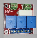
My version of the 10Amp relay board were delivered today.
I opted for cheaper smaller connector for the TTL side and larger higher current for the AC side.
😎That makes wiring a whole lot neater!
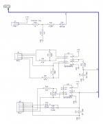
I've got a next generation design ready for testing. It's controlled over I2C and is designed with an AndrewT inspired current saving voltage reducer circuit on the main power relay.
Attachments
Last edited:
I've got a next generation design ready for testing. It's controlled over I2C and is designed with an AndrewT inspired current saving voltage reducer circuit on the main power relay.

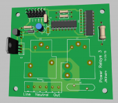
The boards are almost ready for testing. Unfortunately I forgot to order U7 and U1 came in SMD package, so I have to wait until next order from Mouser before I can test them. :/
I enjoyed soldering the SMD parts, I would love to see more of them on later revisions. 🙂
I enjoyed soldering the SMD parts, I would love to see more of them on later revisions. 🙂
Jeff,
Got the files thanx. My mail server thought the mail was spam.
Sent from my HUAWEI MT7-L09 using Tapatalk
Got the files thanx. My mail server thought the mail was spam.
Sent from my HUAWEI MT7-L09 using Tapatalk
Look'n very smart.
I really like your speaker protection and will talk further about a variation when I have more time to sketch up.
Sent from my HUAWEI MT7-L09 using Tapatalk
I really like your speaker protection and will talk further about a variation when I have more time to sketch up.
Sent from my HUAWEI MT7-L09 using Tapatalk
Hi jwilhelm,
Any chance you could share your speaker protection design ?
I am building a 500 w/channel into 8 ohms power amp and am in need of a SERIOUS protector.
Thanks
Any chance you could share your speaker protection design ?
I am building a 500 w/channel into 8 ohms power amp and am in need of a SERIOUS protector.
Thanks
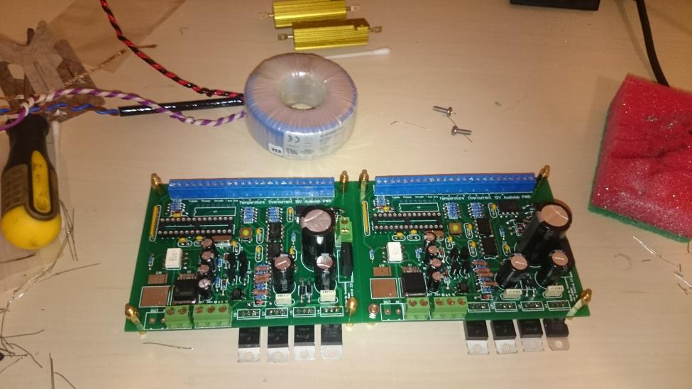
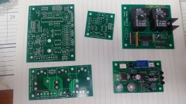
My next evolution of boards have arrived. Lots to test!😎
Looks slick. Will be curious to get your test impressions.
Hello Jeff
greetings thanks for sharing schematic the ghetto version would be great
warm regards
Andrew
greetings thanks for sharing schematic the ghetto version would be great
warm regards
Andrew
Thanx for sharing the schematics jwilhelm 🙂
I love that u have a mosfet relay at the output stage.
Are u by any chance thinking of selling pcb's (like a kit) for this ?
Thanks
I love that u have a mosfet relay at the output stage.
Are u by any chance thinking of selling pcb's (like a kit) for this ?
Thanks
I'll likely have some spare tester boards left over that I can sell. Gerbers are always available too.
- Home
- Amplifiers
- Solid State
- How to build a 21st century protection board