I think an option with speaker impedance testing when it isn't connected is useful .If speaker impedance is under 4 ohm controller no connect.manual speaker "on" , as well ? that's cool !
OS
At the moment it's simpler - it will connect even a zero-ohm piece of wire, but then over-current sensor will shut the amp down at some point.
5 pairs of MT-200s will easily handle 2 ohm 😉
5 pairs of MT-200s will easily handle 2 ohm 😉
A few days ago I had a 2-pair LFET OPS (TubSuMo) output shorted with a thick wire (just a wiring mistake), with over-current sensor disconnected and some small sine wave signal at the input.
I understood something is wrong when I saw nothing at the output and the heatsinks got pretty hot in about one minute (no damages though). If the over-current sensor would be connected, the control board would switch the amp off much earlier.
I understood something is wrong when I saw nothing at the output and the heatsinks got pretty hot in about one minute (no damages though). If the over-current sensor would be connected, the control board would switch the amp off much earlier.
So the above circuit isn't necessary.A few days ago I had a 2-pair LFET OPS (TubSuMo) output shorted with a thick wire (just a wiring mistake), with over-current sensor disconnected and some small sine wave signal at the input.
I understood something is wrong when I saw nothing at the output and the heatsinks got pretty hot in about one minute (no damages though). If the over-current sensor would be connected, the control board would switch the amp off much earlier.
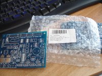
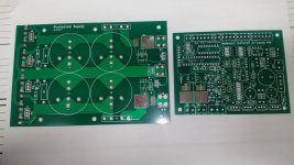
Pcb arrived today!
10 pieces+1 bonus.
Thanks Jeff.
Is there a bom somewhere?
10 pieces+1 bonus.
Thanks Jeff.
Is there a bom somewhere?
Attachments
Last edited:
Pcb arrived today!
10 pieces+1 bonus.
Thanks Jeff.
Is there a bom somewhere?
Search the thread for the schema , (below) is the original BOM/schema.
Jeff's new ones add a few SMD items and have the ATmega328 onboard.
All the linear (PS's, DC , thermal) is the same.
OS
Attachments
Pcb arrived today!
10 pieces+1 bonus.
Thanks Jeff.
Is there a bom somewhere?
Here's a BOM. It wouldn't be complete without a couple stupid mistakes in the silk. C11 and C12 orientation is backwards.😀
Attachments
Last edited:
I haven't had much time to test out these last two versions of the protection board yet. Thing have gotten too busy here since the snow has melted.
R3 and R4 may need some adjustment. They should flow 20mA max but should be close to that to ensure complete on switching of the mosfet relays. R21, R22 and R28 need to be adjusted to make your front panel indicator intensity correct. The listed values aren't great. Do some tuning before finish soldering. Let me know if you have any other questions.
R3 and R4 may need some adjustment. They should flow 20mA max but should be close to that to ensure complete on switching of the mosfet relays. R21, R22 and R28 need to be adjusted to make your front panel indicator intensity correct. The listed values aren't great. Do some tuning before finish soldering. Let me know if you have any other questions.
C11 and C12 orientation is backwards
Sorry what did you mean?
Positive is marked backwards in the silkscreen. Just install those two capacitors backwards to the marking.
Positive is marked backwards in the silkscreen. Just install those two capacitors backwards to the marking.
I was looking at my archived V3.3 schema's - no SS relay schema , just
mechanical.
Do you have the new schema (for the SS section) ?
OS
Hi Jeff ,if it possible, post this protected power supply board.
Are you planning to etch one yourself?
Attachments
Yes,if it is a single side board .Are you planning to etch one yourself?
Yes,if it is a single side board .
I'll redraw it single sided. Give me a bit.
Oh man, i given you troubles🙁I'll redraw it single sided. Give me a bit.
- Home
- Amplifiers
- Solid State
- How to build a 21st century protection board