I would like to do this on a Adafruit Trinket or Pro, should have enough I/O, expecially the bigger ones. Valery, do you have flowchart? The code will be rewritten but I'm interested to see the actual logic flow. I have a similar issue where I need to mate a solid Class A power amp to a tube preamp, and need a complex start sequence. Don't need temperature protection in the amp it has thermistors to stabilise the bias and overcurrent protection (V/I limiting) as well.
p.s I have never programmed anything, so this is an adventure for me. At $10, should still be worth it.
p.s I have never programmed anything, so this is an adventure for me. At $10, should still be worth it.
Valery, I'm thinking about redrawing another compact version of your original protection board. I'd like to use an Atmega328 dip package IC with the Arduino boot loader on it to save space. Do you have the circuit drawn in a sim program? Are there any resistors that can't be replaced with 1/8 watt passives? I might use some SMT too.
Hi Jeff, it would be cool to have it this way 
Resistors - no problem, 1/8W are going to be fine.
My original schematic is in DipTrace - I can send it to you if it will help.
I didn't sim it - just made some calculations - "old style" technique 🙂
Cheers,
Valery
Resistors - no problem, 1/8W are going to be fine.
My original schematic is in DipTrace - I can send it to you if it will help.
I didn't sim it - just made some calculations - "old style" technique 🙂
Cheers,
Valery
I figured by the resistance values compared to voltage none would be running much current.
I don't have DipTrace software. Is there a freeware viewer available for it? I should really draw up a schematic myself with all the modifications I'll be doing anyway. There won't be much room for a very explanatory silk screen when I'm done.
I may have asked this already but you fed the 5 volt regulator off the 12 volt rail. Is that necessary or can it be fed from the raw DC rail? I'm trying to take some load off the 12 volt regulator.
I figured by the resistance values compared to voltage none would be running much current.
I don't have DipTrace software. Is there a freeware viewer available for it? I should really draw up a schematic myself with all the modifications I'll be doing anyway. There won't be much room for a very explanatory silk screen when I'm done.
I may have asked this already but you fed the 5 volt regulator off the 12 volt rail. Is that necessary or can it be fed from the raw DC rail? I'm trying to take some load off the 12 volt regulator.
There is a free version of DipTrace with limitation of 2 layers and 300 points for PCB. However, if you are going to redraw it anyway - probably the attached will be enough? If not - just let me know.
5V regulator can be powered from the raw rail - no problem.
Attachments
I've just downloaded the free version and am playing with it. I've been using Sprint but it's kind of clunky. Your schematic must be close to 300 pins but I'd like to try it out if it will go.
I've just downloaded the free version and am playing with it. I've been using Sprint but it's kind of clunky. Your schematic must be close to 300 pins but I'd like to try it out if it will go.
In your mail 😉
Questions ..... V3.2 Jwilhelm layout.
1. Can you use 1N914 instead of 1N4148 ?
2. Don't see R13 in schema. R13 says 5 space 6K the other 5.6K's say "5K6" ??
3 - C4/6/10 .. not labeled , the PDF schema is hard to see (.01u maybe ?).
4- Where's the darlington buffer in the schema ? ... ULN2003
PS - I don't have a V3.2 schema - where can I get one ?
Also , some diodes/small caps ... I can't read(blind old man) -
they might be the .01's and the
2 separate diodes might be the bzx55c5v1 , can't read them.
I'm sure more questions will arise. 😱
EDIT - are you sure them little orange relays would handle MY amp - with a hard fault ....
or would I turn the contacts into "slag" ???
OS
Last edited:
Questions ..... V3.2 Jwilhelm layout.
1. Can you use 1N914 instead of 1N4148 ?
2. Don't see R13 in schema. R13 says 5 space 6K the other 5.6K's say "5K6" ??
3 - C4/6/10 .. not labeled , the PDF schema is hard to see (.01u maybe ?).
4- Where's the darlington buffer in the schema ? ... ULN2003
PS - I don't have a V3.2 schema - where can I get one ?
Also , some diodes/small caps ... I can't read(blind old man) -
they might be the .01's and the
2 separate diodes might be the bzx55c5v1 , can't read them.
I'm sure more questions will arise. 😱
EDIT - are you sure them little orange relays would handle MY amp - with a hard fault ....
or would I turn the contacts into "slag" ???
OS
1 I think 1N914s should be fine. The circuits are just looking for DC.
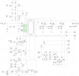
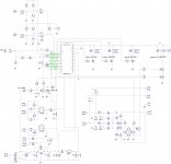
2 R13 is 5k6. I missed changing that value when I did the silk screen. It's the current limiter for D6 in the DC detection circuit, bottom right of the schematic.
3 C4, 6 and 10 are .01. There is a BOM in the PDF. The schematic is very hard to read. I'll attach a jpeg. Easier to zoom in.
4 I haven't drawn a new schematic yet. I'm in the process of learning DipTrace. I hope to do one shortly. The Darlington array replaced Q1, 2 and 10 + base resistors and clamping diodes.
D6 at the center of the rail sense connector is bzx55c5v1. All others are standard diodes.
Valery selected the relays so I can't comment on them but he designed redundancy into everything. If they do happen to weld the amp will already be shut down by the DC offset signal to the Arduino and by the overcurrent or overtemp circuits as well. Really the only thing missing is a crowbar circuit to short the caps out on shutdown but I really don't want one. I have some huge open frame clapper relays that are going to eventually open the rails on my test supply so the caps don't dump into a damaged amp.
Attachments
Very concise answers. Thanks.
This part of the project took on new importance, now that I can apply it to the "Good"
amp. 500$ worth of Dayton woofers demands it.
I looked at the little yellow caps you included. The Chinese are so inconsistent with
cap coding ... it says "01K-100" (cant see a point).
The zeners ... I don't know ... but they have .85 V forward drop as opposed to
a 1n914 .6V drop. There were only 2 of these separate. I might have to break out
my little toroid for a 40V supply and apply a dropping resistor to these (measure
voltage).
OS
Those are Nichicon polyester .01yF 100 volt caps. K is the tolerance. I can't remember it off the top of my head. Some consistancy would be nice. The zeners are BZX55C5V1 for D6. I think I sent 2. They are 5.1 volts so a 9 volt battery should be enough to test.
Last edited:
I've never properly tested the thermal shutoff yet. I think Valery said with as built resistors will trip around 90 C. Probably a little late for bjts. I think R20 and 28 set the trip point. In the next redesign I might set both with a common reference.
I've never properly tested the thermal shutoff yet. I think Valery said with as built resistors will trip around 90 C. Probably a little late for bjts. I think R20 and 28 set the trip point. In the next redesign I might set both with a common reference.
Thermal is set with an external mje 340 - BE junction to earth?
That would make the thermal adjust "hairy". reducing R28/20 < 10K raises
the LM393 reference point . A 20K- 10 turn trimmer would be nice here. 🙂
PS - 5K trimmer for both in series with a fixed 6.8K would allow <60C - 90+C
....a 10K would at least drop the trip point to <80C.
OS
Pots are great if you don't have kids around who like to adjust them when you aren't looking. A pot and an Arduino that close together is a disaster waiting to happen around my place.
Your kids would adjust the pots !! 😀 whoa...
Mine are trained to not touch any project with a lit LED , the reason I put LED's
on everything -- LED = DEATH ! 😱
They DO like to solder components , that can't kill you.
OS
Mine are trained to not touch any project with a lit LED , the reason I put LED's
on everything -- LED = DEATH ! 😱
They DO like to solder components , that can't kill you.
OS
It's all good until they're teenagers. That's when they know more than you do. That's why the Arduino usb port is pointed at the transformer too. Not an oversight.
They need an example - turn a screwdriver into molten slag with a 1KVA
power supply. Say , "that could of been you". Or.. how a charged 100Kuf 80V cap
bank can blow your fingertips off ! 😀 .
OS
power supply. Say , "that could of been you". Or.. how a charged 100Kuf 80V cap
bank can blow your fingertips off ! 😀 .
OS
I know how that would end. "OH Cool! Do it again!" My kids are fine. The bosses kid and his minions are the problem. Not much hope of teaching them anything.
Hi guys, sorry I've been out of discussion for some time 😉 Those business trips...
You're right, R20 and 28 set the trip point, defining the reference level for comparators.
Trip temperature needs to be tested and probably adjusted. I don't think it's going to trip frequently, but as a "last resort"... for situation when all offset and current levels are still OK, but it's getting hot - good thing to have 😉
- Home
- Amplifiers
- Solid State
- How to build a 21st century protection board