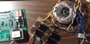
You actually stuff your boards backwards. It's easier to start with all the low level parts like resistors and diodes first, then keep adding vertically. It gives you much better access with your soldering iron plus you can flip the board over and the table will hold your component in place.
You actually stuff your boards backwards. It's easier to start with all the low level parts like resistors and diodes first, then keep adding vertically. It gives you much better access with your soldering iron plus you can flip the board over and the table will hold your component in place.
I did this one that way , on the "spooks" I did as you say..
I designed those and had no questions. 😎
Parts were all over the place .... young children were playing with them. 😱
Get as many "pretty parts" away from curious hands at once.
The big stuff is fun , my eyes are going for the small stuff.
Wiring up deadly power supplies is my specialty ( GE instrumentation tech) -
build many $$ worth of over-designed equipment - they had a killer shop , too.
OS
Hi Val. 🙂 What joy of revisiting all my old analog sensor "blocks".
??? - The AC sense , only have 270K for R8/R9.
Q9 should have enough beta to pull it's collector down with the slight higher Z input ?
OS
270K should be ok - less than 10% difference, no problem 😉
What if I just mounted a heatsink made of flashing across all 4 to-220's.
Actually, the 2 lm78xx regs have a tabbed grounds -good . Dang ! that poor 7812 is
running all those "monster" OMRON relays - big flashing from corner screw to corner screw !! 😱
PS - you run the "monsters" right from the ULN2003 ? Does IT get hot at 158ma
X 2 (both omrons)? 😱
OS
I'm running them on a common heatsink, however - as already mentioned - 7812 is the most stressed component here. All the keys are fully open, so - low voltage drop = low heating, but 12V regulator gets pretty hot... Athough, the heatsink works well, keeping it under control.
Then , as it is now fully populated - I can fire it up ?
Hook the led up , it should cycle through it's startup sequence - see no faults (nothing hooked up) and finish ?
I did notice on the relay page of the PDF , the controller is hooked direct to
main amp AC , then a "power on" relay .... lastly , the inrush omron across the big
power resistor (PDF shows the inrush first - error ?).
PS - did you get credited by Digikey ?
OS
I think the pdf is correct. The inrush relay is connected in series with the power resistor and is turned on before the main relay which bypasses the resistor.
There's probably no need to keep the inrush relay active after the power relay is engaged. Possibly a way to reduce the load on the 12 volt regulator.
There's probably no need to keep the inrush relay active after the power relay is engaged. Possibly a way to reduce the load on the 12 volt regulator.
Then , as it is now fully populated - I can fire it up ?
Hook the led up , it should cycle through it's startup sequence - see no faults (nothing hooked up) and finish ?
I did notice on the relay page of the PDF , the controller is hooked direct to
main amp AC , then a "power on" relay .... lastly , the inrush omron across the big
power resistor (PDF shows the inrush first - error ?).
PS - did you get credited by Digikey ?
OS
Hi OS,
Jeff is right - you need the main amp rails to be connected, othervise the offset sensor will not work properly and the startup sequence will be interrupted.
It is assumed that inrush goes first, connecting the big trafo via the resistor, then goes power-on, shortening that resistor, then, after some time, the speakers get connected.
The led is dimmed during standby, a bit brighter during startup and full power when "Ready".
I've got the credit notification on Thursday, it went to Digikey account - trying to fugure out how I can use it for ordering the snap-on caps (I don't see it in the system)... I'll be back from Switzerland on Wednesday (another business trip 🙂) - will contact Digikey again to clarify 😉
Cheers,
Valery
I think the pdf is correct. The inrush relay is connected in series with the power resistor and is turned on before the main relay which bypasses the resistor.
There's probably no need to keep the inrush relay active after the power relay is engaged. Possibly a way to reduce the load on the 12 volt regulator.
Ah! Jeff, good idea 🙂 Just didn't think about it. We can connect the main power relay, so that it will bypass both the resistor and the inrush relay. Of course! Then we can switch the inrush off after the main one is on and reduce the load. I will amend the algorythm for this option as soon as I'm back home

Hi OS,
Jeff is right - you need the main amp rails to be connected, othervise the offset sensor will not work properly and the startup sequence will be interrupted.
It is assumed that inrush goes first, connecting the big trafo via the resistor, then goes power-on, shortening that resistor, then, after some time, the speakers get connected.
The led is dimmed during standby, a bit brighter during startup and full power when "Ready".
I've got the credit notification on Thursday, it went to Digikey account - trying to fugure out how I can use it for ordering the snap-on caps (I don't see it in the system)... I'll be back from Switzerland on Wednesday (another business trip 🙂) - will contact Digikey again to clarify 😉
Cheers,
Valery
LLS2A682MELC Nichicon | 493-6173-ND | DigiKey - or any other 35 X 52mm snap- in . No more room - have the
case/PCB already designed for it.
It is assumed that inrush goes first, connecting the big trafo via the resistor, then goes power-on, shortening that resistor, then, after some time, the speakers get connected.
This is confusing ? Normally (on my last big amp) ,The main power switch would
be in place of the first relay (on the left) , charging the caps through the resistor/trafo .. then after a few seconds the relay in parallel across the big resistor would engage
-allowing for the full deadly power supply (after the caps charged).
On my analog version , I used the rails to charge an R/C triggering this relay (3 sec.).
OS
Ah! Jeff, good idea 🙂 Just didn't think about it. We can connect the main power relay, so that it will bypass both the resistor and the inrush relay. Of course! Then we can switch the inrush off after the main one is on and reduce the load. I will amend the algorythm for this option as soon as I'm back home
Hook em' in parallel !! 😎 then just reprogram the sequence ...
So , relay 1 + resistor on (soft start) - then relay 2 on after inrush (relay 1 then turns off) - saving 158ma. Good thinking , J !
Edit what I wanted to know with this controller - the amps main power switch is just the trigger for the controller. No
need for a big 10A power switch ... right ?
OS
Last edited:
I think, confusion comes from the naming 🙂
I call "inrush relay" the one that goes on first, connecting the trafo through the resistor. The other one, going on after inrush, is the main one... 🙄
I call "inrush relay" the one that goes on first, connecting the trafo through the resistor. The other one, going on after inrush, is the main one... 🙄
Here is another relay to consider using in place of the Omrons. It's a very rugged automotive type relay with a lower current draw and a smaller footprint. The only thing I'm not stuck on is the blade connections but I've used them for 15 years and have never had a failure.
Attachments
$4 each is nice too.
I've got a new version of the board down to 4" x 3". Just need to figure out how to clean up the silk screen now. DipTrace is neat but the default silks are nasty.
I've got a new version of the board down to 4" x 3". Just need to figure out how to clean up the silk screen now. DipTrace is neat but the default silks are nasty.
I have a "rail sense" question.. It is not on the schema .... + / 0 /- maybe ? the 5V
zener is the middle euro-block terminal and a 4.7K/22K for the outside 2. hmmm?
(below) I could take the chance ... but the designers are here - patience.
PS - 37-0-37vdc is the PS , will it do to test this ?
OS
zener is the middle euro-block terminal and a 4.7K/22K for the outside 2. hmmm?
(below) I could take the chance ... but the designers are here - patience.
PS - 37-0-37vdc is the PS , will it do to test this ?
OS
Attachments
Positive rail goes to the square pad, left looking at it. Ground center, - right side. Likely anything above 20 volts will do it.
Then the order .... controller on first - then fire up the rails ? to simulate a "real "
startup scenario...
OS
startup scenario...
OS
As long as it has rail voltage before 3 seconds after the main power relay closes it will be fine. You can power up the rails ahead of time or power them through the relay. Try it with the rails unhooked and you can see what to expect with DC offset.
- Home
- Amplifiers
- Solid State
- How to build a 21st century protection board